Machine tool

a technology of machine tools and tools, applied in the field of machine tools, can solve the problems that the front side doors cannot be opened and closed alone, and achieve the effect of production and safety assuran

Active Publication Date: 2015-12-24
MAKINO MILLING MASCH CO LTD
View PDF9 Cites 11 Cited by
  • Summary
  • Abstract
  • Description
  • Claims
  • Application Information

AI Technical Summary

Benefits of technology

[0006]Further, the objective of the present invention is to provide a machine tool with a compact and convenient splashguard improved to ensure the safety and the efficiency of manual tool change and a preparation during machining with a double-sided workpiece mount.
[0011]According to the present invention, the preparation chamber side door (front door) and the machining chamber side door (lateral side door) can be separately opened and closed in the same direction, and therefore selectively opened and closed as needed. The provision of a door locking switch which allows selectively the opening and closing of the preparation chamber side door (front door) and the machining chamber side door (lateral side door) depending on opening and closing patterns provides convenient door opening and closing patterns, for example, allowing the doors to be opened only when the spindle of a machine tool and supply of the machining liquid are deactivated whereby the effect of the production and the safety are ensured.

Problems solved by technology

However front side door cannot be singly opened and close.
Therefore, it encounters a problem that all of the doors must be opened in order to access the front part of a machining region, and accordingly any design of interlock must deactivate completely the machining process by deactivating the rotation of spindle and the supply of machining liquid.

Method used


Image

  • Machine tool
  • Machine tool
  • Machine tool

Examples


Embodiment Construction

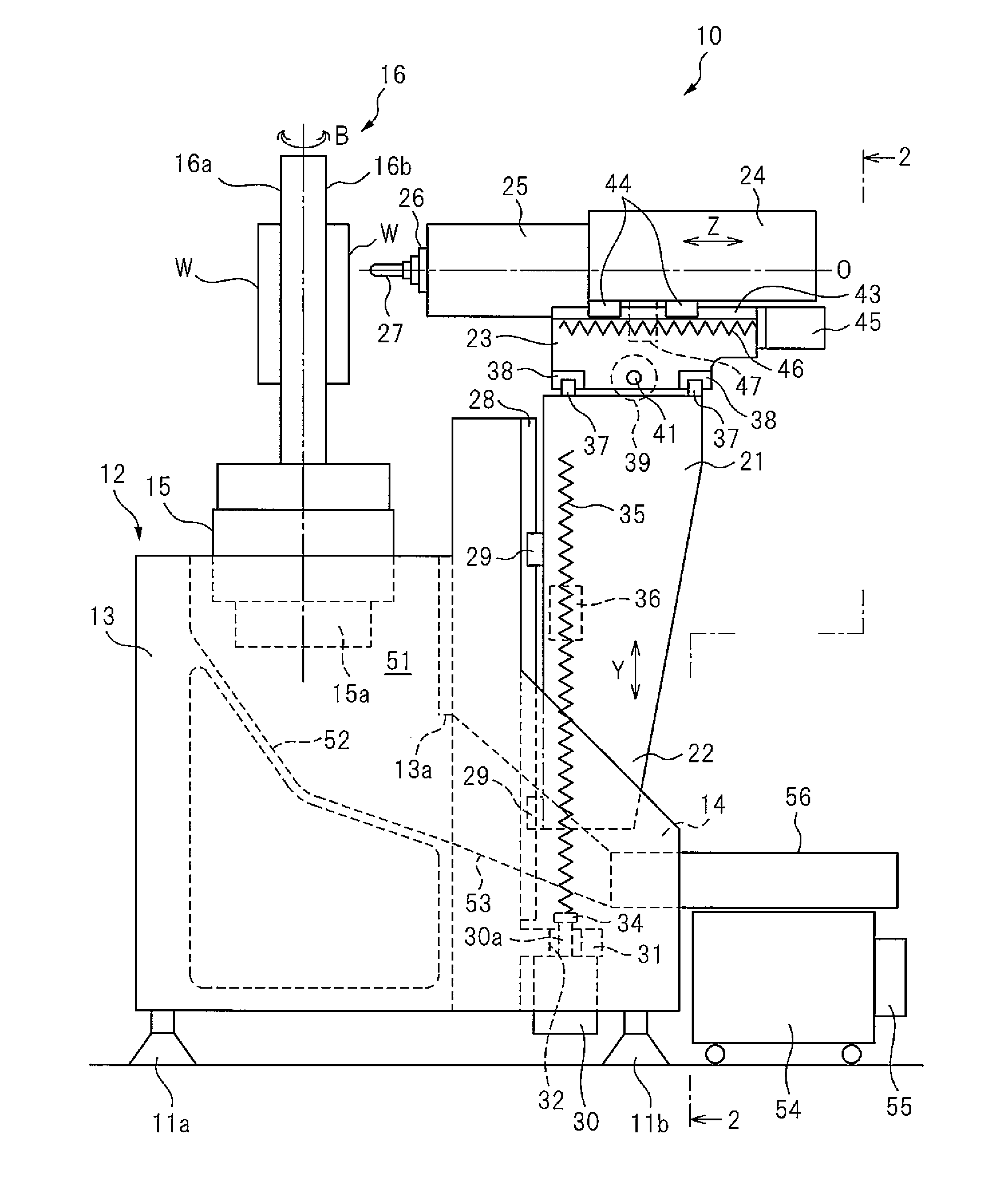
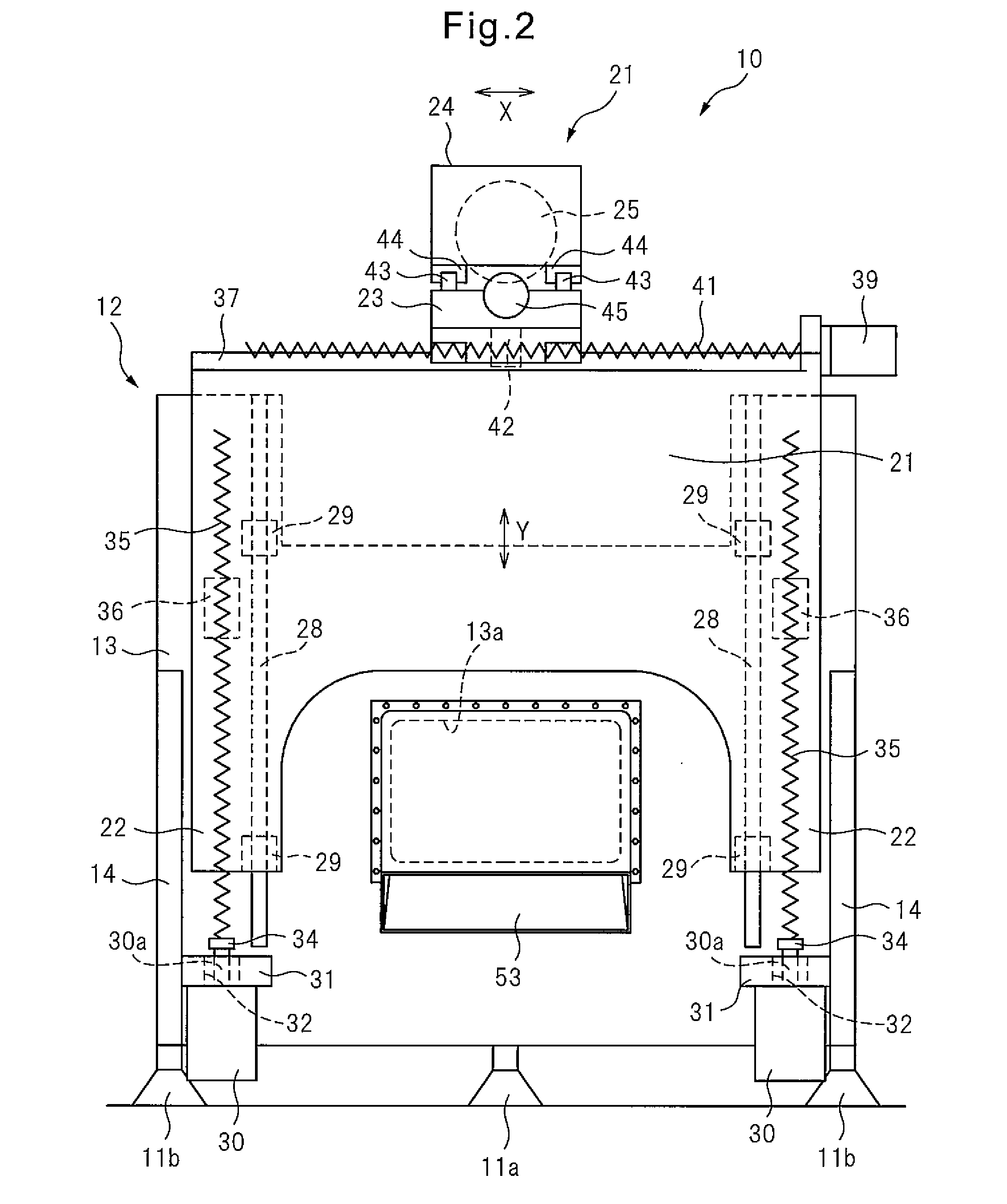
[0016]With reference to the drawings, an embodiment of the invention will be described below. FIG. 1 is a side view schematically showing the structure of a machine tool according to an embodiment of the invention. FIG. 2 is a rear view of the machine tool viewing in the direction of arrows 2-2 in FIG. 1. FIG. 3 is a perspective view schematically showing the exterior of the machine tool with a splashguard. FIG. 4 is a partial sectional view of the splashguard of FIG. 3 showing sliding doors according to an embodiment of the invention. In this specification, a front side of the machine tool is defined by the direction of the tip of a tool attached to the end of a spindle as described below.

[0017]In this embodiment, as an example, a machine tool 10 may be a four-axis horizontal machining center having liner feed axes extending in three orthogonal X-, Y- and Z-axes directions and a B-axis providing a rotary feed axis. The left-right direction (perpendicular to the plane of FIG. 1) of ...


PUM

PropertyMeasurementUnit
structureaaaaaaaaaa
heightaaaaaaaaaa
lengthaaaaaaaaaa

Abstract

A work-machine splash guard for enclosing a space for machining a workpiece, and preventing the spraying of chips and machining fluid, is equipped with: a front-surface door for opening and closing in the horizontal direction via an arc-shaped movement, and positioned on the front-surface side of the work machine; a side-surface door for opening and closing by performing an arc-shaped movement that is concentric with the front-surface door, and overlapping with the front-surface door; and door-locking switches for selectively allowing the opening / closing of the front-surface door and the side-surface door according to an opening / closing pattern.

Description

CROSS REFERENCE TO RELATED APPLICATIONS[0001]This application is a U.S. National Phase patent application of PCT / JP2012 / 066185, filed on Jun. 25, 2012, which is hereby incorporated by reference in the present disclosure in its entirety.FIELD OF THE INVENTION[0002]The invention relates to a machine tool, in particular a machine tool provided with a splashguard for preventing chips and machining liquid from scattering during machining of a workpiece under NC (numerical control).BACKGROUND OF THE INVENTION[0003]Conventionally, splashguards, enclosing machine tools, have been used in order to prevent chips and machining liquid from scattering during machining in machine tools. Splashguards generally are provided with a door provided in a front panel or a side panel in order to access a tool attached to the end of a spindle or a workpiece which is machined by the tool. For example, Patent Document 1 discloses a machine tool cover provided with a plurality of arcuate doors.Patent Document...

Claims


Application Information

Patent Timeline
Patent Type & Authority Applications(United States)
IPC IPC(8): B23Q11/08B23Q1/66B23Q11/00B23Q1/01
CPCB23Q1/66B23Q11/0089Y10T409/30392B23Q1/015B23Q11/0891B23Q11/0053B23Q11/0057B23Q11/0067B23Q1/017F16P3/02Y02P70/10Y10T74/2191Y10T74/2193Y10T74/2194Y10T409/401925B23B7/10B23B25/04B23Q11/08B23Q11/0816B23Q11/0825B23Q11/0883F16P3/10
Inventor SUZUKI, TOSHIHIROKAZUYA, MAYUMIARAKI, IZUMI
Owner MAKINO MILLING MASCH CO LTD
Why Eureka
Try Eureka