Fluid Boundary Layer Control

a technology of fluid boundary layer and control layer, applied in the field of fluid mechanics, can solve the problem of low separation and pressure drag

Inactive Publication Date: 2016-01-14
VIRES AERONAUTICS
View PDF0 Cites 8 Cited by
  • Summary
  • Abstract
  • Description
  • Claims
  • Application Information

AI Technical Summary

Problems solved by technology

Additionally, low separation creates pressure dr

Method used


Image

  • Fluid Boundary Layer Control
  • Fluid Boundary Layer Control
  • Fluid Boundary Layer Control

Examples


embodiment

Retrofit Embodiment

[0080]In certain embodiments, the techniques described herein serve as an inventive template for those skilled in the art to understand the broader scope of this application and for implementation in all types of objects. Certain embodiments can include rods being held in fixed positions along the outside contour of an object (or, perhaps, within an inside contour of an object, if that inside contour impacts or is impacted by a fluid). The rods can be held by bearings and powered by any kind of suitable rotary power source. A belt can be wrapped around the rods and driven like a conveyor. The key distinction in this implementation, as contrasted to others described elsewhere in this application, is that nothing need be directly embedded into the object. It is simply attached directly to the outside of the object (i.e., as in a retrofit). The size and power requirements vary among objects. It can be governed, for example, by the mission objectives, design constrain...

embodiments

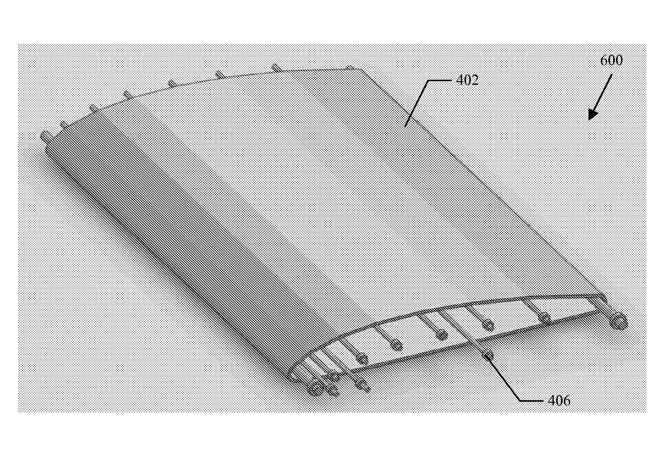
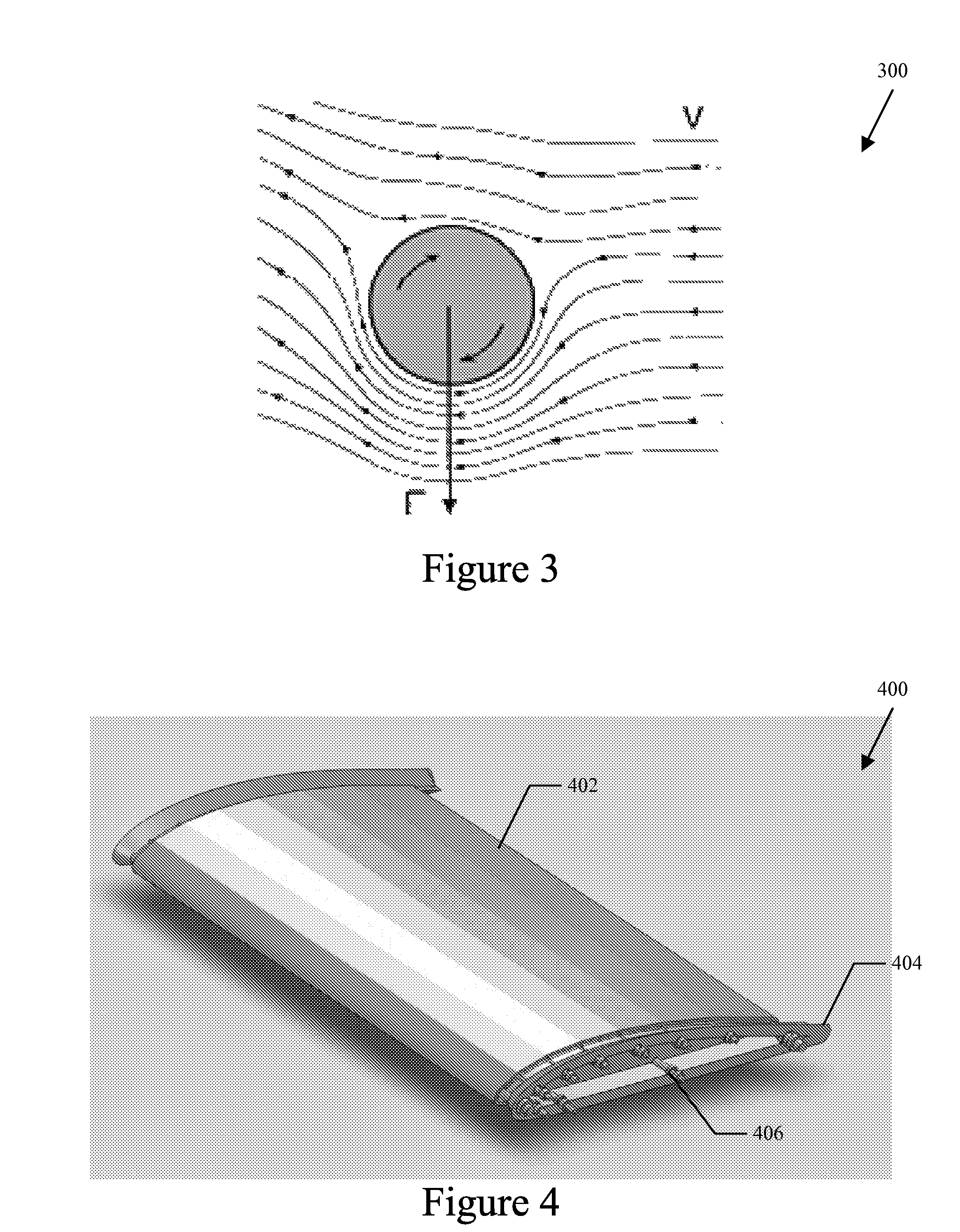
[0086]A1. An apparatus adapted to control flow of a fluid boundary layer, comprising: an aircraft wing housing, having a chord length, a leading edge and a trailing edge; at least one bearing element, disposed on an interior portion of the aircraft wing housing, disposed between a first endplate and a second endplate, substantially parallel to the chord length of the aircraft wing housing; at least one rod member, adapted to fit into the at least one bearing element, extending substantially parallel to the chord length of the aircraft wing housing; and a rotational belt, disposed on an outer surface of the aircraft wing housing, having an inner surface comprising a first coefficient of friction and an outer surface comprising a second coefficient of friction, wherein the inner surface is operationally coupled to the at least one rod member and the outer surface of the rotational belt is in mechanical contact with the fluid boundary layer.

[0087]A2. The apparatus of embodiment A1, fur...


PUM


Abstract

The lift and drag performance of all vehicles is strongly influenced by viscous effects, and in turn, laminar separation bubbles. This application employs an effective fluid boundary layer control strategy that reduces parasitic drag, allows for more usable angles of attack, and delays or stops separation. In the approach of this application, the control surface effectively uses the Magnus effect to delay or stop a separation bubble from forming, which can increase lift, reduce drag, and delay degrees of stall by directly manipulating the velocity gradient in the fluid boundary layer.

Description

PRIORITY CLAIM[0001]This application claims the benefit of priority from U.S. Provisional Patent Application Ser. No. 61 / 768,412, entitled “VIRES Control Surface” and filed Feb. 23, 2013, and also claims the benefit of priority from U.S. Provisional Patent Application Ser. No. 61,900,721, entitled “Fluid Boundary Layer Control” and filed Nov. 6, 2013, both of which are fully incorporated herein by reference for all purposes to the extent permitted by law and not inconsistent with this application.BACKGROUND[0002]1. Field of the Application[0003]The disclosure is directed to fluid mechanics and, more particularly, to controlling a fluid boundary layer of an object in a fluid medium.[0004]2. Background of the Disclosure[0005]Virtually all aspects of daily life involve fluids and things that move through fluids. Air and water are the two most dominate fluids on the planet, through which most things move. A thin layer of fluid surrounding an object is generally referred to as a fluid bo...

Claims


Application Information

Patent Timeline
IPC IPC(8): B64C3/14B64C1/38B64C23/08
CPCB64C3/141B64C1/38B64C23/08Y02T50/10
Inventor GOEL, HARSHIL
Owner VIRES AERONAUTICS
Why Eureka
Try Eureka