Portable cleanroom printing cabinet

a printing cabinet and cleanroom technology, applied in the direction of pile separation, transportation and packaging, pile separation, etc., can solve the problems of inability to pre-print, sterilize and package the remainder of the document introduced into the sterile environment in a timely fashion, and the inability to readily obtain information

Active Publication Date: 2016-01-28
VALTEK ASSOC INC
View PDF7 Cites 14 Cited by
  • Summary
  • Abstract
  • Description
  • Claims
  • Application Information

AI Technical Summary

Problems solved by technology

However, paper and paper products are a significant contamination source due to shedding fibers, particulates and microorganisms (e.g., bacillus and mold).
However, the remainder of the documents introduced into sterile environments cannot be pre-pri

Method used


Image

  • Portable cleanroom printing cabinet
  • Portable cleanroom printing cabinet
  • Portable cleanroom printing cabinet

Examples


Embodiment Construction

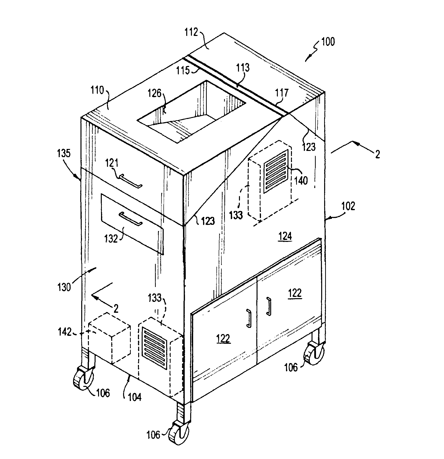
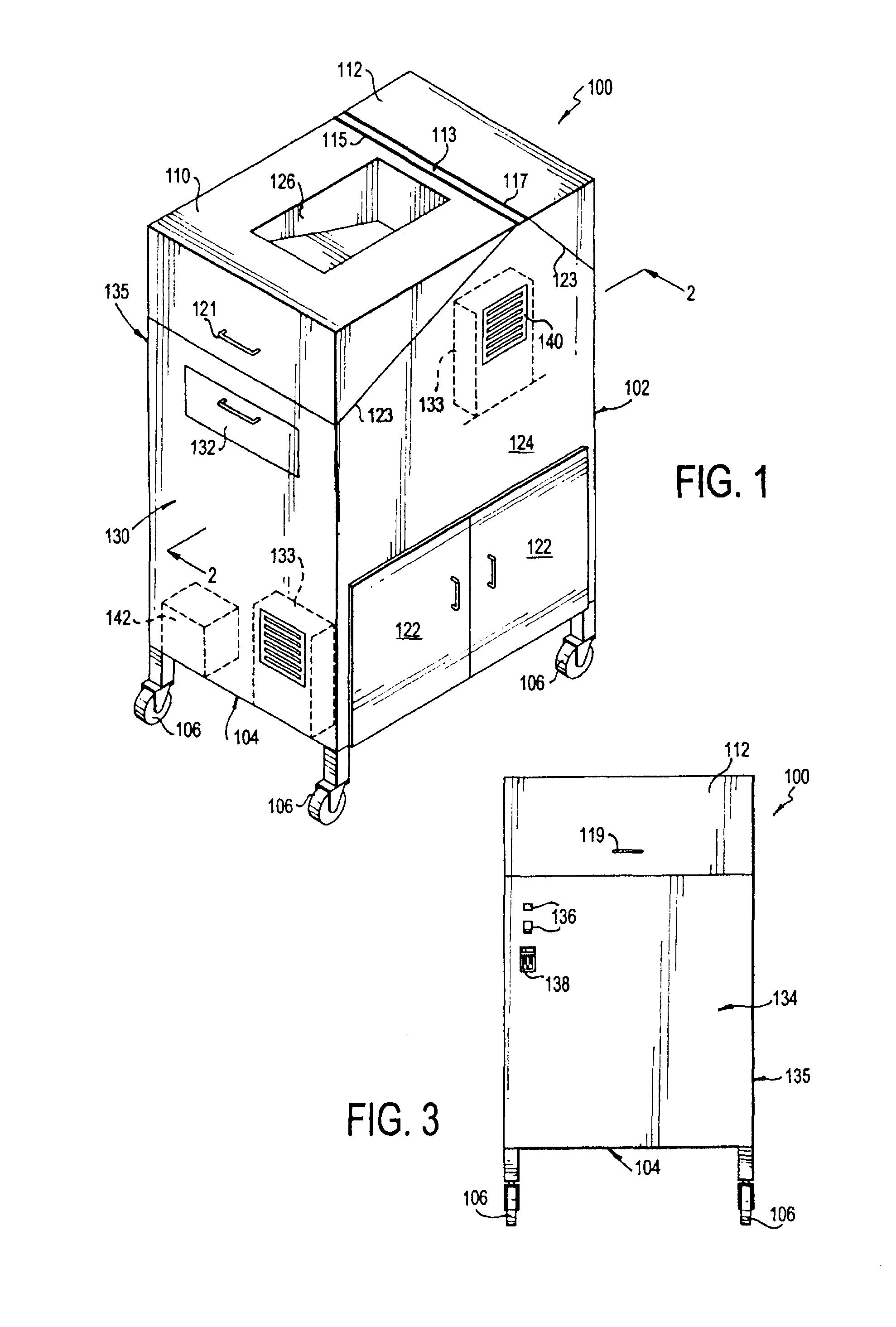
[0016]Referring to FIGS. 1-3, the portable printing cabinet 100 of the invention allows the printing of documents within a controlled, cleanroom environment onto sterilized paper at high speeds. This cabinet reduces or eliminates the presence of bioburden (e.g., microorganisms such as bacillus and mold) on printed documents. The printing cabinet 100 further assures that particulates and shedding fibers from the paper is minimized or eliminated. The printing cabinet 100 of the invention may be used in any ISO level controlled area, including cleanrooms at an ISO 5 level or lower.

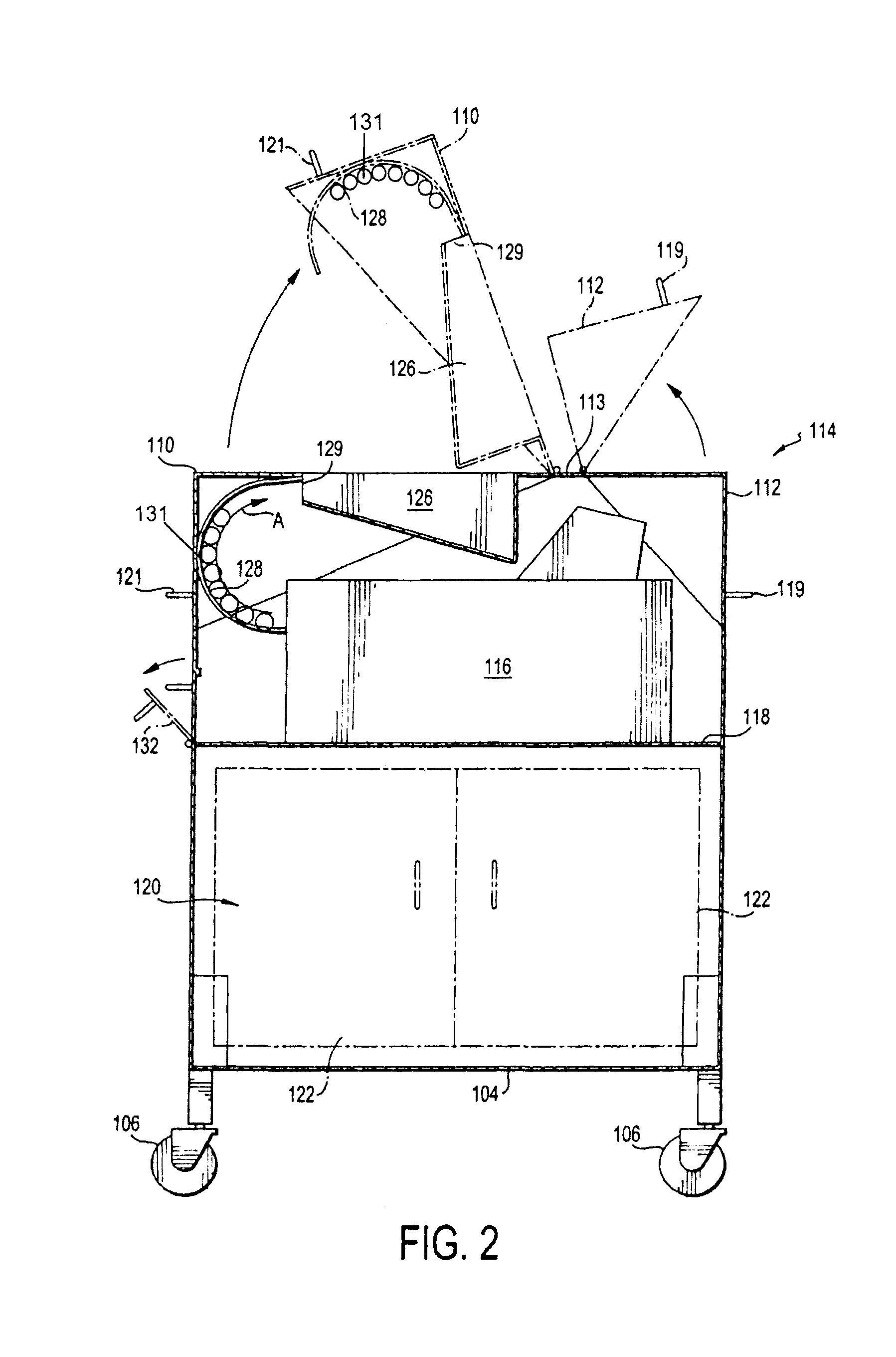
[0017]As shown in FIG. 1, the printing cabinet 100 generally includes a housing 102 having at least four sides and a bottom 104. In the embodiment shown, the four sides are formed of thin rectangular-shaped panels and include a left side 130, front side 124, right side 134, and back side 135. The sides 124, 130, 134 and 135 are preferably joined with the bottom 104 of the housing 102 to form a substantially r...


PUM


Abstract

A portable printing cabinet having a housing with a substantially enclosed interior and an opening formed in a side surface thereof, a printing device located within the interior of said housing, and a paper tray positioned outside of the housing and in communication with the opening of the housing is provided.

Description

CROSS-REFERENCE TO RELATED APPLICATION[0001]The invention is a continuation-in-part of co-pending U.S. Patent Application No. 14 / 033,045, filed Sep. 20, 2013, the disclosure of which is hereby incorporated by reference.FIELD OF THE INVENTION[0002]The invention relates to a portable printing cabinet for use in a sterile environment. In particular, the invention provides a multi-compartment printing unit that can be used in a cleanroom without introducing outside contaminants such as particulates and microorganisms.BACKGROUND OF THE INVENTION[0003]Sterile “cleanroom” environments demand that any person or item entering the room be free of a certain level of contaminants. Sterilized environments are most commonly designed for use in manufacturing facilities and medical research and treatment facilities in the pharmaceutical, biotechnology, and healthcare industries, to name a few. Sterile cleanroom environments may be classified under a variety of classification schemes, including the ...

Claims


Application Information

Patent Timeline
IPC IPC(8): B41J29/377B65H31/00
CPCB65H31/00B41J29/377A47B31/02A47B81/00B41J29/13B41J29/06B41J29/12B41J29/02
Inventor VELLUTATO, JR., ARTHUR
Owner VALTEK ASSOC INC
Why Eureka
Try Eureka