Method for performing system power control within an electronic device, and associated apparatus

Active Publication Date: 2016-02-25
MEDIATEK INC
View PDF8 Cites 6 Cited by
  • Summary
  • Abstract
  • Description
  • Claims
  • Application Information

AI Technical Summary

Benefits of technology

The present invention is a method and apparatus that can improve the performance of electronic systems with fewer side effects. It allows for proactive power budgeting and management, reducing peak power and optimizing battery resource allocation. Compared to conventional architectures, which are reactive, the present invention can prevent related problems. Overall, it achieves fine-grained thermal control and adaptive battery resource allocation.

Problems solved by technology

A conventional portable electronic device, such as a mobile phone, a wearable device, a tablet, etc., may suffer from the peak power consumption and the peak thermal impact problems (e.g. due to high instantaneous power consumption), where the peak power consumption may hurt the battery life of the conventional portable electronic device and may cause the system thereof to be unstable, and the unacceptable peak thermal impact may be dangerous to the user of the conventional portable electronic device.
But, when the battery supply voltage starts to drop (e.g. the battery supply voltage may be less than 3.8 V), the tolerance to peak power is getting worse, and therefore, any peak power may cause the system failure.
However, further problems may be introduced.
For example, the conventional methods measure results brought by peak power, thus are reactive but not proactive and may have poor response time.
In addition, monitoring the peak IR drop may be inaccurate, resulting in greater and greater hardware area overhead to improve accuracy.
Additionally, the sampling rate is typically limited, and therefore, it is hard to monitor at a full speed.

Method used


Image

  • Method for performing system power control within an electronic device, and associated apparatus
  • Method for performing system power control within an electronic device, and associated apparatus
  • Method for performing system power control within an electronic device, and associated apparatus

Examples


Embodiment Construction

[0023]Certain terms are used throughout the following description and claims, which refer to particular components. As one skilled in the art will appreciate, electronic equipment manufacturers may refer to a component by different names. This document does not intend to distinguish between components that differ in name but not in function. In the following description and in the claims, the terms “include” and “comprise” are used in an open-ended fashion, and thus should be interpreted to mean “include, but not limited to . . . ”. Also, the term “couple” is intended to mean either an indirect or direct electrical connection. Accordingly, if one device is coupled to another device, that connection may be through a direct electrical connection, or through an indirect electrical connection via other devices and connections.

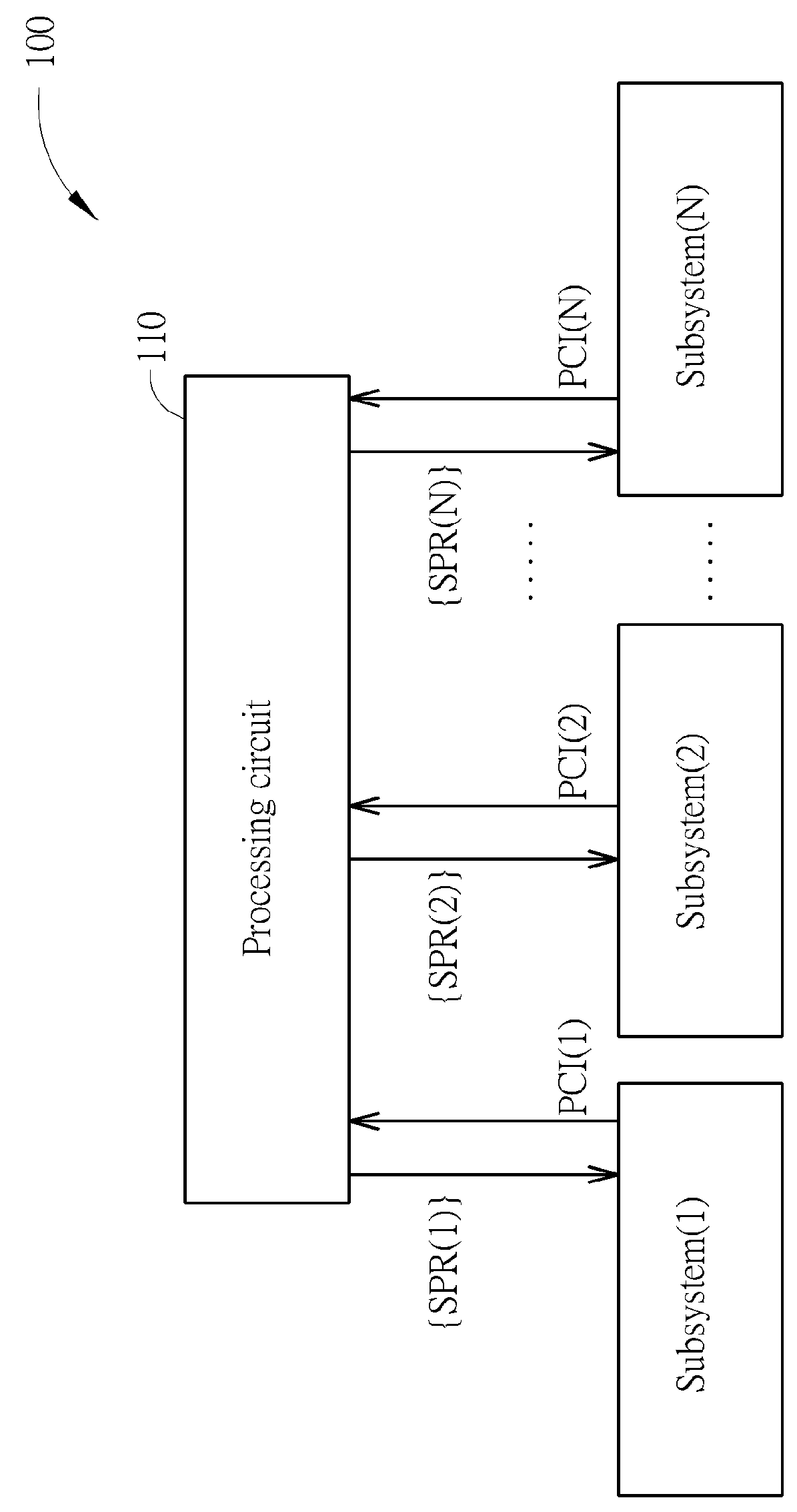
[0024]FIG. 1 is a diagram of an apparatus 100 for performing system power control within an electronic device according to an embodiment of the present invention, ...


PUM


Abstract

A method for performing system power control within an electronic device and an associated apparatus are provided. The method includes the steps of: utilizing a power consumption index generator positioned in a specific subsystem to generate a power consumption index corresponding to the specific subsystem, where the electronic device includes a plurality of subsystems, and the specific subsystem is one of the plurality of subsystems; and triggering a power limiter protection operation for the electronic device according to the power consumption index. For example, the power consumption index corresponding to the specific subsystem may represent a power consumption value of the specific subsystem, and the method may further include: comparing the power consumption value of the specific subsystem with a peak power threshold to determine whether the power consumed by the specific subsystem reaches the peak power threshold to generate a determining result, for triggering the power limiter protection operation.

Description

CROSS REFERENCE TO RELATED APPLICATIONS[0001]This application claims the benefit of U.S. Provisional Application No. 61 / 971,896, which was filed on Mar. 28, 2014, and is included herein by reference.FIELD OF INVENTION[0002]The present invention relates to power consumption control of a system comprising multiple subsystems, and more particularly, to a method for performing system power control within an electronic device, and an associated apparatus.BACKGROUND OF THE INVENTION[0003]A conventional portable electronic device, such as a mobile phone, a wearable device, a tablet, etc., may suffer from the peak power consumption and the peak thermal impact problems (e.g. due to high instantaneous power consumption), where the peak power consumption may hurt the battery life of the conventional portable electronic device and may cause the system thereof to be unstable, and the unacceptable peak thermal impact may be dangerous to the user of the conventional portable electronic device. For...

Claims


Application Information

Patent Timeline
IPC IPC(8): G06F1/10G06F1/32
CPCG06F1/10G06F1/324G06F1/206G06F1/3206G06F1/3212G06F1/3296Y02D10/00G06F1/3228G06F1/329
InventorLU, CHIA-LINWANG, HUI-HSUANNIU, I-PUCHANG, YU-CHUNGSHIEH, JIA-HORNG
OwnerMEDIATEK INC