Rotary gyroscope

Active Publication Date: 2006-05-16
SAMSUNG ELECTRONICS CO LTD
View PDF17 Cites 36 Cited by
  • Summary
  • Abstract
  • Description
  • Claims
  • Application Information

AI Technical Summary

Benefits of technology

[0009]Therefore, in an effort to solve at least some of the above-mentioned problems, it is a feature of an embodiment of the present invention to provide a rotary gyroscope that is capable of sensing angular velocities of a plurality of axes in a plane, in which a motion of a driven unit or element is d

Problems solved by technology

Although there are conventional micro-gyroscopes that can measure an input angular velocity normal to a center plane thereof, which may be easily fabricated and driven, these conventional micro-gyroscopes have a disadvantage in that they are not able to detect angular velocities of more than two axes in a plane.
These other conventional micro-gyroscopes, however, present several varying problems.
For example, these conventional micro-gyroscopes may experience

Method used


Image

  • Rotary gyroscope
  • Rotary gyroscope
  • Rotary gyroscope

Examples


Example

[0038]Korean Patent Application No. 2003-14106, filed on Mar. 6, 2003, and entitled: “Rotary Gyroscope,” is incorporated by reference herein in its entirety.

[0039]The present invention will now be described more fully hereinafter with reference to the accompanying drawings, in which a preferred embodiment of the invention is shown. The invention may, however, be embodied in different forms and should not be construed as limited to the embodiments set forth herein. Rather, these embodiments are provided so that this disclosure will be thorough and complete, and will fully convey the scope of the invention to those skilled in the art. Like numbers refer to like elements throughout.

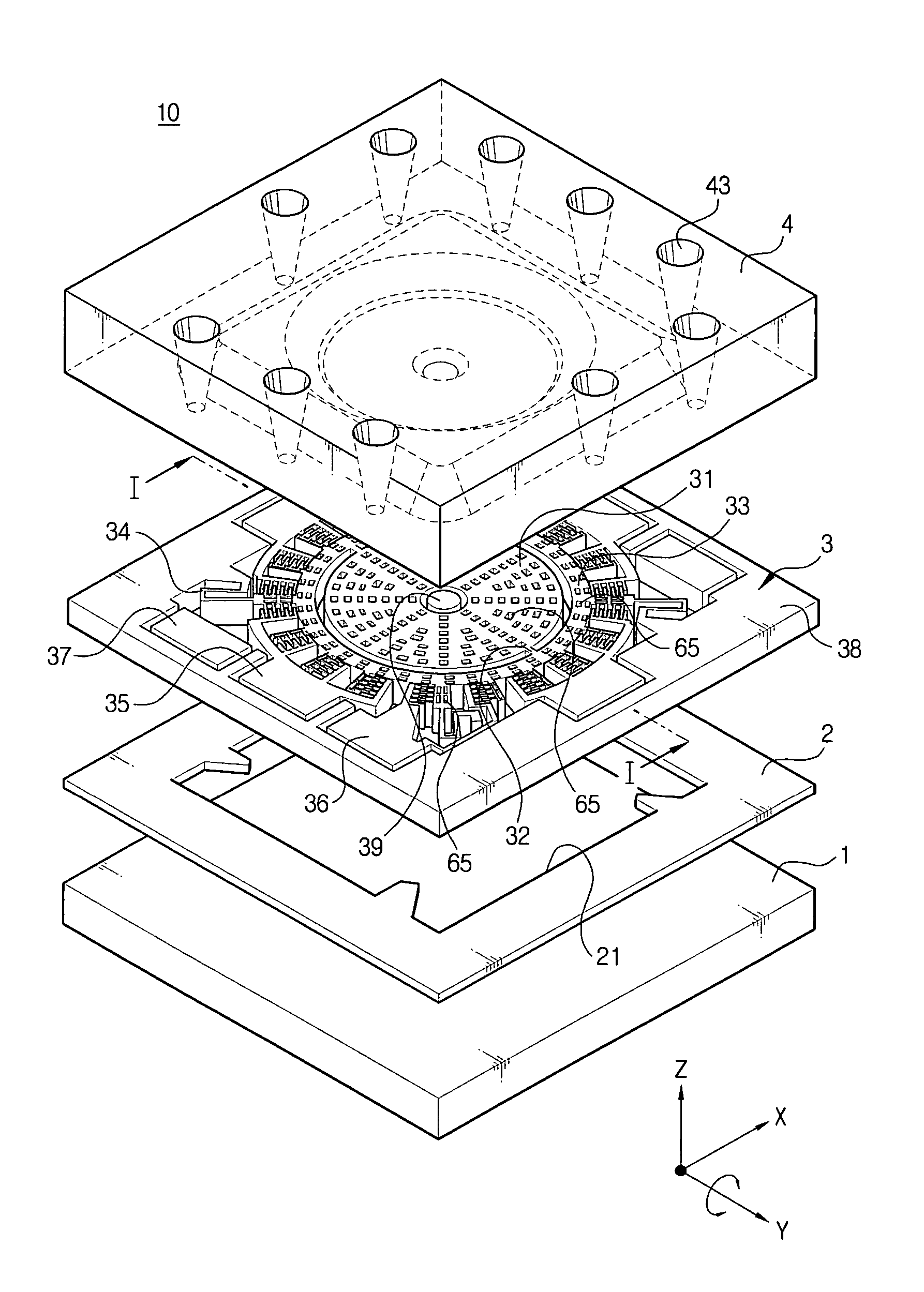
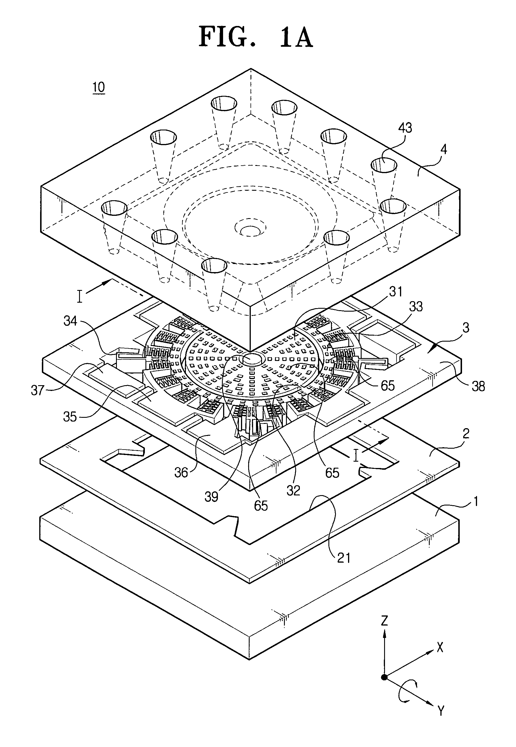
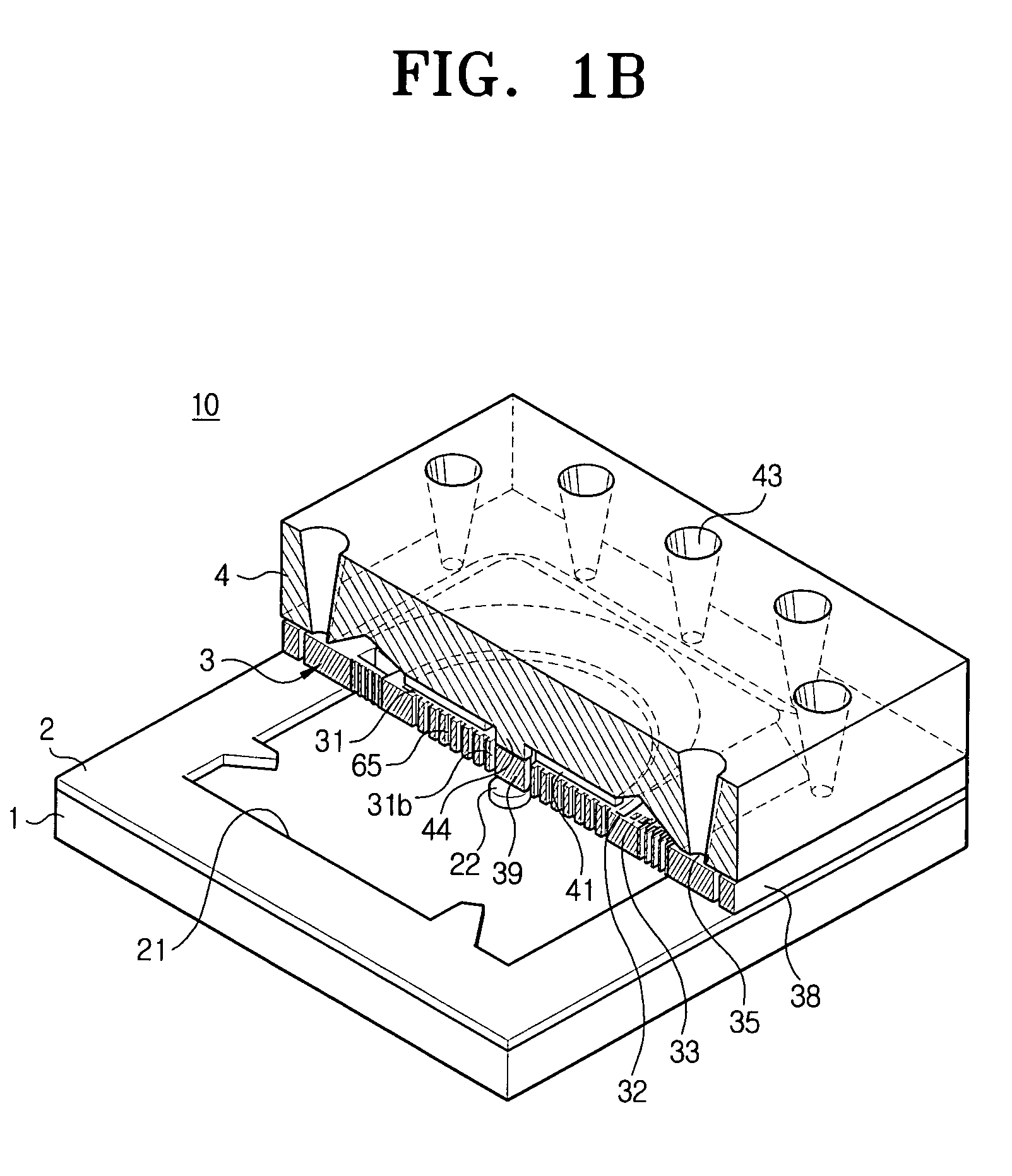
[0040]FIGS. 1A and 1B illustrate an exploded perspective view and a partially cutaway perspective view of a rotary gyroscope 10 in accordance with a preferred embodiment of the present invention.

[0041]Referring to FIGS. 1A and 1B, the rotary gyroscope 10 includes a base plate 1, an insulator 2 disposed on th...


PUM


Abstract

A rotary gyroscope includes a base plate, an intermediate structure, including a driven element floating over the base plate and supported by a driving supporter radially extending therefrom, the driven element performing an oscillating motion with respect to a first axis, which is normal to a center plane thereof, a driving electrode driving the driven element, and a sensing element disposed in the driven element and connected to the driven element by a sensing connector to oscillate together with the driven element and concurrently to perform a sensing motion with respect to a third axis, which is normal to the first axis and any second axis, which is parallel to a center plane, due to a Coriolis force when an angular velocity is inputted from the second axis, and a cover covering the intermediate structure and having a sensing electrode to detect the sensing motion of the sensing element.

Description

BACKGROUND OF THE INVENTION[0001]1. Field of the Invention[0002]The present invention relates to a gyroscope for sensing an angular velocity using a rotational resonance motion of a mass moving in a regular angle. More particularly, the present invention relates to a rotary gyroscope capable of sensing a plurality of angular velocities corresponding to a plurality of axes in a plane.[0003]2. Description of the Related Art[0004]Generally, a gyroscope detects a rotational angular velocity by changing a displacement of a mass due to a Coriolis force into a change in capacitance, based on a principle that when a mass oscillating or rotating in a direction of a first axis is applied with a force of rotating in a constant angular velocity from a direction of a second axis, which is normal to the first axis, the Coriolis force acts on the mass in a direction of a third axis, which is normal to both the first axis direction and the second axis direction.[0005]Such a gyroscope is currently i...

Claims


Application Information

Patent Timeline
IPC IPC(8): G01P9/04G01C19/02G01C19/56G01C19/5642G01C19/5712
CPCG01C19/5642G01C19/02
Inventor JEONG, HEE-MOONSONG, IN-SEOBKANG, SEOK-JIN
Owner SAMSUNG ELECTRONICS CO LTD
Why Eureka
Try Eureka