Position calculating system and haulage vehicle

a technology of position calculation and position calculation, which is applied in surveying and navigation, navigation instruments, instruments, etc., can solve problems such as inability to solve and reduce the accuracy of position calculation

Active Publication Date: 2016-03-10
NIHON KENKI CO LTD
View PDF15 Cites 57 Cited by
  • Summary
  • Abstract
  • Description
  • Claims
  • Application Information

AI Technical Summary

Problems solved by technology

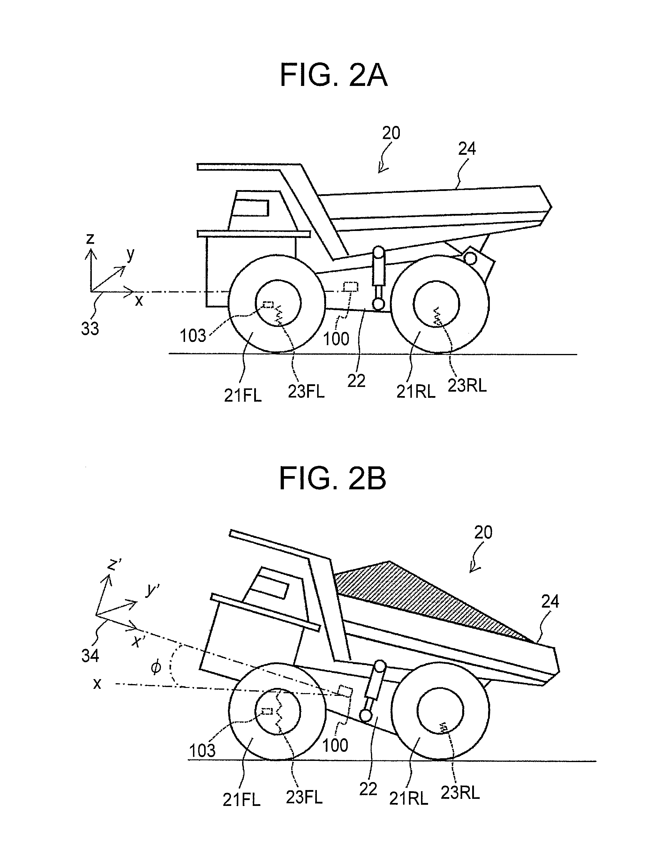
If an inertial measurement unit is mounted on the body frame of the mining dump truck and dead reckoning is applied for the calculation of the position of the mining dump truck in the above-described situation, a problem arises that an inclination of the body frame affects outputs from a gyro sensor and acceleration sensor and the effects of this inclination lead to a reduction in the accuracy of the position calculation.
However, the techniques described in U.S. Pat. No. 6,959,240 B2 and U.S. Pat. No. 6,895,313 B2 cannot solve the above-described problem, because they are correction techniques in which the inclination of a body frame in a loaded state is not taken into consideration.

Method used


Image

  • Position calculating system and haulage vehicle
  • Position calculating system and haulage vehicle
  • Position calculating system and haulage vehicle

Examples


second embodiment

of First Aspect

[0099]A second embodiment of the first aspect will next be described with reference to FIG. 9. In the first embodiment, the correction amount is calculated by the recursive least squares method every time when changed from an unloaded state to a loaded state (see step S806 in FIG. 8). In the second embodiment, on the other hand, a correction amount M for correcting an inclination of the body frame is first determined uniquely under the premise that the inclination angles of the body frame do not change practically every time when changed from an unloaded state to a loaded state. As the maximum loading capacity of the dump truck 20 is specified, this embodiment is preferred when the loaded state at the time of full loading is substantially constant and a load is loaded without being extremely biased to one side in the lateral or longitudinal of the body.

[0100]As the flow of processing in the second embodiment is substantially the same as that in the first embodiment ex...

first embodiment

of Second Aspect

[0106]A first embodiment of the second aspect uses a suspension pressure of the vehicle in the loading state determination processing instead of using the access map. The remaining configurations and processing details are similar to those in the first and second embodiments of the first aspect, and therefore their descriptions are omitted herein. With reference to FIGS. 10 and 11, a description will hereinafter be made about the first embodiment of the second aspect. FIG. 10 is a functional block diagram depicting the internal configuration of a dump truck according to the first embodiment of the second aspect. FIG. 11 is a flow chart showing the flow of loading state determination processing in the first embodiment of the second aspect.

[0107]As depicted in FIG. 10, at least one of the front left suspension, front right suspension, rear left suspension and rear right suspension of a dump truck 20 according to the first embodiment of the second aspect is provided wit...


PUM


Abstract

Disclosed is a position calculating system for a haulage vehicle including wheels and a body frame mounted on the wheels. The system includes an attitude detection sensor fixed on the body frame, a wheel rotational speed sensor, a loading status information acquiring unit, a correction amount setting unit, a velocity vector calculating unit, and a position calculating unit. The loading status information acquiring unit acquires loading status information indicating whether the body frame is in a loaded state or in an unloaded state . The correction amount setting unit calculates, based on the attitude information, a correction amount required for bringing detection axes in the loaded state into coincidence with corresponding detection axes in the unloaded state. The velocity vector calculating unit calculates the velocity vector of the haulage vehicle. The position calpulating unit calculates a position of the haulage vehicle by using the velocity vector.

Description

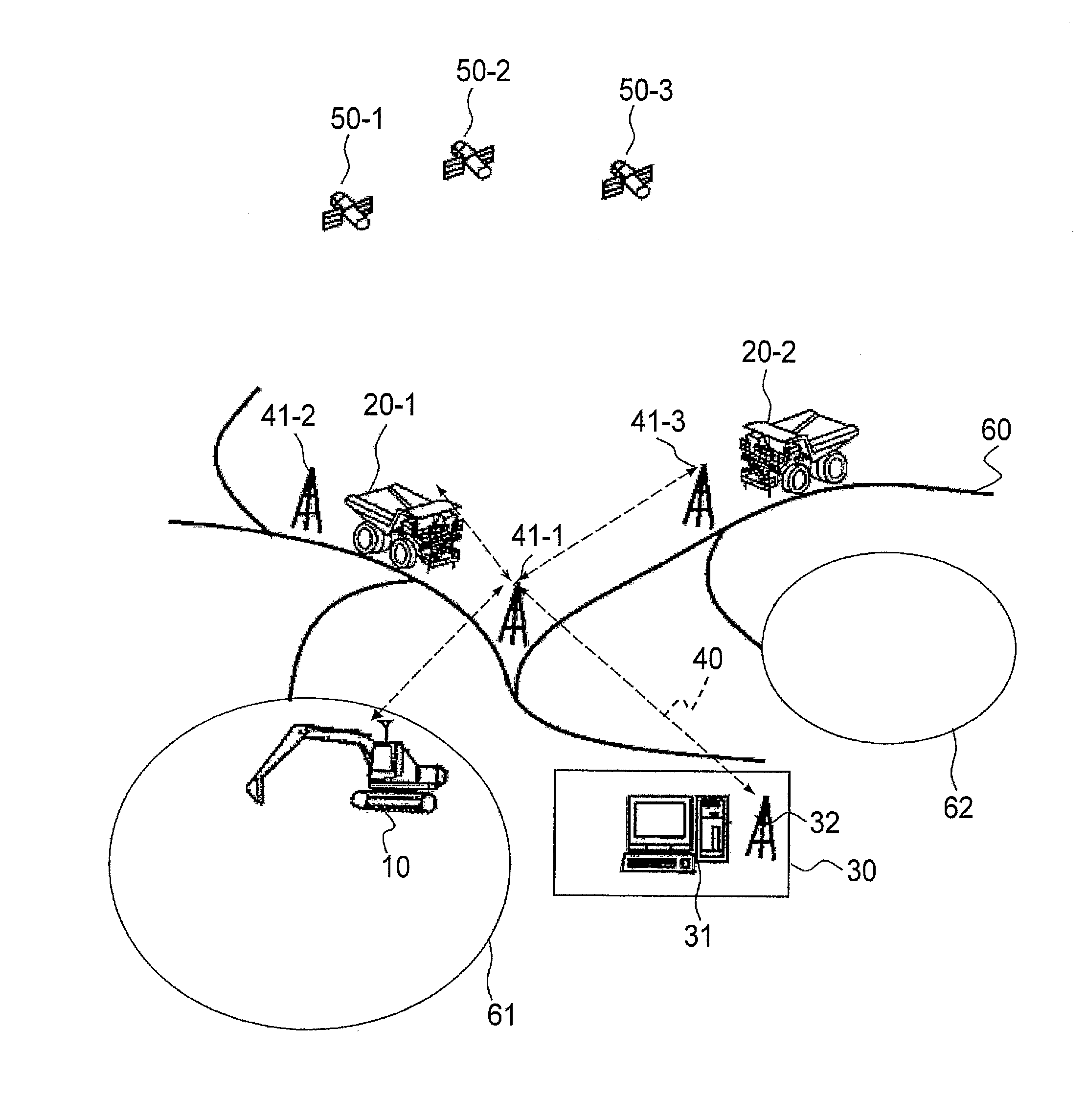
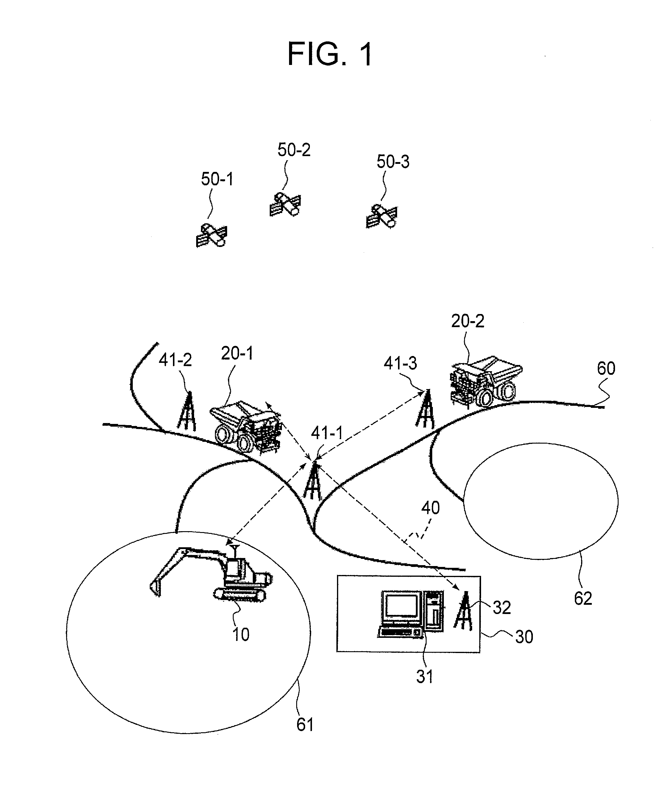
CROSS-REFERENCE TO RELATED APPLICATION[0001]This application claims the priority of Japanese Patent Application 2014-180456 filed Sep. 4, 2014, which is incorporated herein by reference.BACKGROUND OF THE INVENTION[0002]1. Field of the Invention[0003]This invention relates to a position calculating system and a haulage vehicle, and especially to improvements in or relating to the accuracy of a position calculation upon calculation of the position of a mining dump truck by dead reckoning that uses an inertial measurement unit (IMU).[0004]2. Description of the Related Art[0005]As a technology for the calculation of the position of a vehicle, there is employed a technology that like a GPS (Global Positioning System) or the like, measures its real coordinates on the earth. For this position calculation by the GPS or the like, the reception of positioning radio waves transmitted from geolocation satellites is indispensable.[0006]However, the positioning radio waves may be blocked by a str...

Claims


Application Information

Patent Timeline
Patent Type & Authority Applications(United States)
IPC IPC(8): G01B21/00G01P3/00
CPCG01P3/00G01B21/00G01C21/16
Inventor BANDO, MIKIOISHIMOTO, HIDEFUMISAITO, SHINJIRO
Owner NIHON KENKI CO LTD
Why Eureka
Try Eureka