Retractable row crop tire guard

a tire guard and rear-row technology, applied in the field of agricultural vehicles, can solve the problems of large crop loss, heavy weight, and long installation time of the current crop shield on the agricultural implement,

Active Publication Date: 2016-05-12
AGCO CORP
View PDF2 Cites 13 Cited by
  • Summary
  • Abstract
  • Description
  • Claims
  • Application Information

AI Technical Summary

Problems solved by technology

However, the wheels of the vehicle can run over and crush the crop that extends into the aisles, resulting in significant crop loss.
However, current crop shields are bulky, heavy and take many hours to install onto an agricultural implement.

Method used


Image

  • Retractable row crop tire guard
  • Retractable row crop tire guard
  • Retractable row crop tire guard

Examples


Embodiment Construction

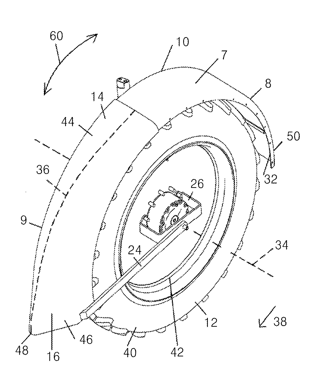
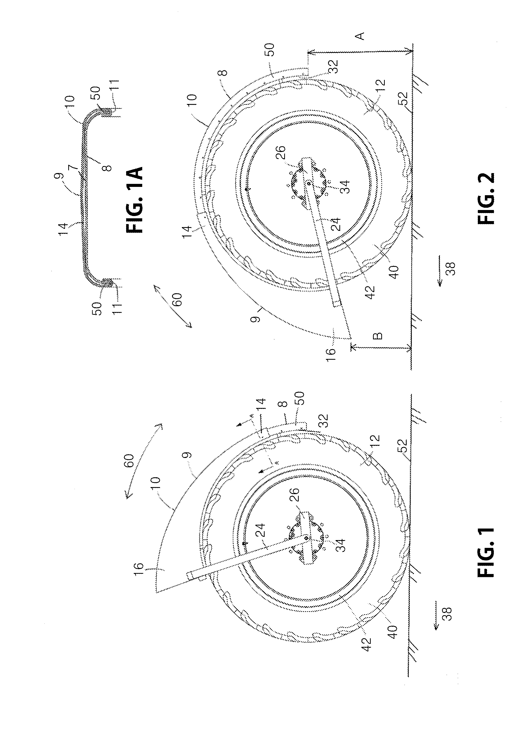
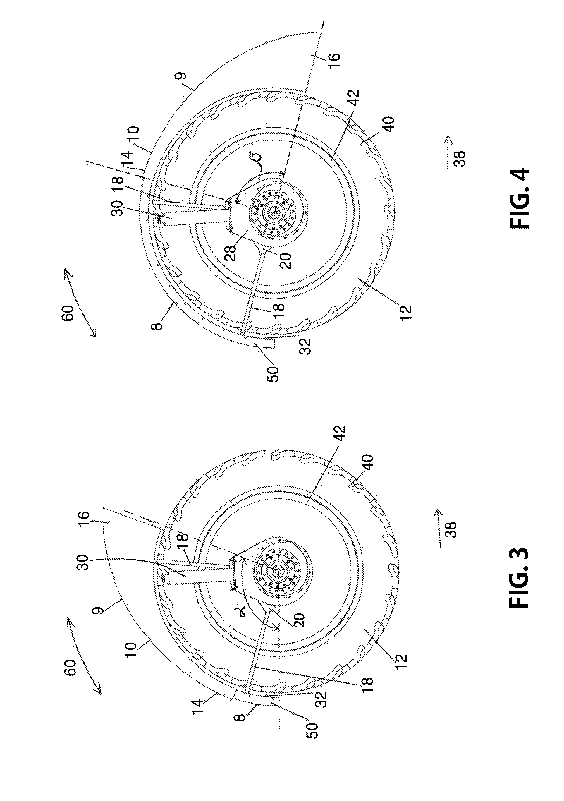
[0022]The present disclosure is directed to a retractable tire guard 10 that allows an operator to move a portion of the tire guard 10 over a wheel 12, such as by a pivoting motion, for example, to change between a fender configuration and a crop shield configuration. FIGS. 1-6 show an exemplary tire guard 10 designed for use with the ground-engaging wheel 12 of an agricultural vehicle, such as a sprayer or tractor that is movable in a travel direction across a crop field. Such a tire guard 10 may be formed of rubber, plastic, metal or a combination thereof. Tire guard 10 includes fender portion 8 and crop shield portion 9.

[0023]In FIGS. 1, 3 and 5, crop shield portion 9 is retracted over fender portion 8, so that tire guard 10 serves as a fender to prevent mud, rocks and other debris from being picked up by the wheel 12 and thrown upward onto the agricultural vehicle. In the illustrated fender configuration of FIGS. 1, 3 and 5, a major portion of the fender portion 8 is covered by ...


PUM


Abstract

A tire guard for a wheel of an agricultural vehicle includes a fender having a first width substantially covering a width of the wheel and a crop shield having a forward area and a back area. A first bracket connects the fender to the wheel and a second bracket connects the crop shield to the wheel. The crop shield is movable over the fender between a first position and a second position. In the first position, the forward area of the crop shield is disposed proximate an upper portion of the wheel and the back area of the crop shield is disposed proximate a rear portion of the wheel. In the second position, the forward area of the crop shield is disposed proximate a front portion of the wheel and the back area of the crop shield is disposed proximate an upper portion of the wheel.

Description

RELATED APPLICATION[0001]Under provisions of 35 U.S.C. §119(e), Applicant claims the benefit of U.S. Provisional Application No. 62 / 077,541, entitled RETRACTABLE ROW CROP TIRE GUARD and filed Nov. 10, 2014, which is hereby incorporated by reference.BACKGROUND OF THE INVENTION[0002]1. Field of Invention[0003]The present invention relates generally to agricultural vehicles movable in a travel direction through a field of row-planted crops, and more particularly, to a tire guard for use with a ground-engaging wheel of an agricultural vehicle[0004]2. Description of Related Art[0005]The plants of certain row crops, such as corn, cotton and soybeans, for example, can branch out and block the aisles between the planted rows when fully matured. For some crops, spacing between rows may be about 15-30 inches, though wide variation is possible. When harvesting machinery enters the field, the vehicle (e.g., tractor, harvester, sprayer, etc.) proceeds with its wheels placed between the rows. How...

Claims


Application Information

Patent Timeline
Patent Type & Authority Applications(United States)
IPC IPC(8): A01D65/08B60R19/38B62D25/16A01B76/00B62D25/18
CPCA01D65/08A01B76/00B60R2019/002B62D25/16B60R19/38B62D25/182
Inventor RAU, JEREMIAH T.SNYDER, TODD B.
Owner AGCO CORP
Why Eureka
Try Eureka