Controlled Pressure Drilling System with Flow Measurement and Well Control

Active Publication Date: 2016-05-19
WEATHERFORD TECH HLDG LLC
View PDF1 Cites 27 Cited by
  • Summary
  • Abstract
  • Description
  • Claims
  • Application Information

AI Technical Summary

Benefits of technology

[0032]To selectively distribute the drilling fluid flow through the one or more flowmeters, a determination can be made of which of the one or more flowmeters to select for distribution by comparing a measured flow rate, a measured pressure, and the like to a capacity for each of the flowmeters. Additionally, th

Problems solved by technology

However, the typical mass flowmeter 24 inherently loses accuracy at a low end of the flow measurement scale due to internal losses.
Unfortunately, there are some disadvantages associated with the Coriolis mass flowmeter 24.
In addition to some of the physical limitations, the Coriolis mass flowmeter 24 used in MPD operations has some limitations related to its measurement capabilities.
Additionally, the Coriolis mass flowmeter 24 is limited to taking measurements of fluid with low gas content.
Another

Method used


Image

  • Controlled Pressure Drilling System with Flow Measurement and Well Control
  • Controlled Pressure Drilling System with Flow Measurement and Well Control
  • Controlled Pressure Drilling System with Flow Measurement and Well Control

Examples


Embodiment Construction

A. System Overview

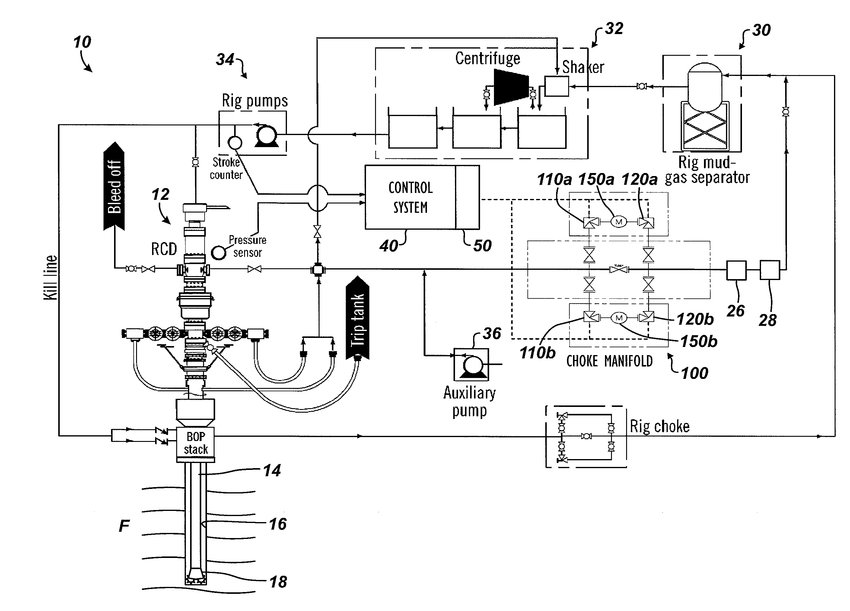
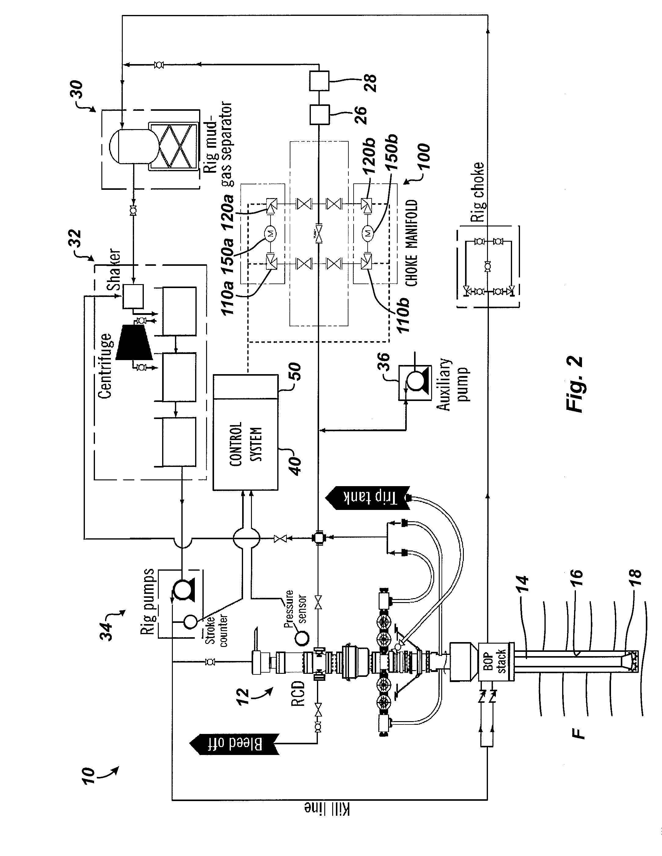
[0054]FIG. 2 shows a closed-loop drilling system 10 according to the present disclosure for controlled pressure drilling. As shown and discussed herein, this system 10 can be a Managed Pressure Drilling (MPD) system and, more particularly, a Constant Bottomhole Pressure (CBHP) form of MPD system. Although discussed in this context, the teachings of the present disclosure can apply equally to other types of controlled pressure drilling systems, such as other MPD systems (Pressurized Mud-Cap Drilling, Returns-Flow-Control Drilling, Dual Gradient Drilling, etc.) as well as to Underbalanced Drilling (UBD) systems, as will be appreciated by one skilled in the art having the benefit of the present disclosure.

[0055]The drilling system 10 of FIG. 2 has a number of similarities to the system already discussed in FIG. 1. For instance, the drilling system 10 has a rotating control device (RCD) 12 from which a drill string 14, a bottom hole assembly (BHA), and a drill bit 18 e...


PUM


Abstract

A drilling system for drilling a wellbore has one or more valves or chokes to control the upstream pressure of drilling fluid flow in a controlled pressure drilling operation. A measurement is obtained of the drilling fluid flow from the wellbore. Based on the obtained measurement, the drilling fluid flow is selectively distributed with a distributor through one or more of a plurality of flowmeters, such as Coriolis meters. A reading of the drilling fluid flow is obtained from the selected flowmeter(s). Upstream pressure in the drilling fluid flow is controlled with the one or more valve based at least in part on the reading from the one or more selected flowmeters. The reading can be a flow rate, a pressure, or the like compared to capacities of the flowmeters. Additional valves downstream of the flowmeters can be controlled based on cavitation that the valves are estimated to produce.

Description

CROSS-REFERENCE TO RELATED APPLICATIONS[0001]This application claims the benefit of U.S. Prov. Appl. 62 / 080,847, filed 17 Nov. 2014, which is incorporated herein by reference.BACKGROUND OF THE DISCLOSURE[0002]FIG. 1 shows a closed-loop drilling system 10 according to the prior art for controlled pressure drilling. The drilling system 10 has a rotating control device (RCD) 12 from which a drill string 14, a bottom hole assembly (BHA), and a drill bit 18 extend downhole in a wellbore 16 through a formation F. The rotating control device (RCD) 12 atop the BOP contains and diverts annular drilling returns to create the closed loop of incompressible drilling fluid.[0003]The system 10 also includes mud pumps 34, a standpipe (not shown), a mud tank 32, a mud gas separator 30, and various flow lines, as well as other conventional components. In addition to these, the drilling system 10 includes an automated choke manifold 20 that is incorporated into the other components of the system 10.[0...

Claims


Application Information

Patent Timeline
IPC IPC(8): E21B21/08E21B21/10E21B7/00
CPCE21B21/08E21B21/106E21B7/00E21B33/128E21B33/129E21B33/1293E21B33/134
Inventor DILLARD, WALTER S.NORTHAM, PAUL R.GEORGE, GERALD G.VIERAITIS, DAVID J.
Owner WEATHERFORD TECH HLDG LLC
Why Eureka
Try Eureka