
Butterfly Valve Seal Retaining Arrangement

Active Publication Date: 2016-05-19
KENNEDY VALVE
View PDF1 Cites 3 Cited by
  • Summary
  • Abstract
  • Description
  • Claims
  • Application Information

AI Technical Summary

Benefits of technology

The invention is a butterfly valve with a rotatable operating stem and a valve seal arrangement including a seal flange, seal channel, elastomeric seal, and annular seal retaining ring. The elastomeric seal is held in a compressed state between the annular seal retaining ring and the seal flange and defines a seal surface held compression against the vane seat of the vane when the vane is in the first position. The annular seal retaining ring is introduced into the cylindrical flow channel and positioned in the seal channel using an annular press die and an annular expansion die. The technical effect of this invention is to provide a reliable seal against the vane seat for the butterfly valve and improved performance and stability in the valve's operation.

Problems solved by technology

Such constructions, however, do not facilitate field replacement of the elastomeric seal, and also may not provide for adjustment of the elastomeric seal.
Additionally, experience has shown that bonded elastomeric seal interfaces may fail under high flow velocity conditions.
This type of construction increases machining required during construction of the hollow valve body, and therefore also manufacturing costs.
However, this method of construction limits the types of elastomers that may be used to form the elastomeric seals because not all elastomeric materials lend themselves to these manufacturing techniques.
As a result, butterfly valves used to regulate flow in fluid systems carrying aggressive chemicals may require short service intervals between elastomeric seal replacements.
For example, in clean water treatment facilities that use concentrated sterilization fluids to clean piping systems, improper flushing of the sterilization fluids after a cleaning cycle may lead to rapid elastomeric seal degeneration, and failure of elastomeric seals.

Method used


Image

  • Butterfly Valve Seal Retaining Arrangement
  • Butterfly Valve Seal Retaining Arrangement
  • Butterfly Valve Seal Retaining Arrangement

Examples


Embodiment Construction

[0034]A butterfly valve seal arrangement of the type described herein provides several advantages over the prior art. An elastomeric seal is preferably formed from commercially available bulk O-ring cord, which results in a broader range of elastomeric materials being available to choose from in constructing the elastomeric seal, allowing the construction of elastomeric seals that are more compatible with a range of aggressive fluids. Additionally, the elastomeric seal provides greater resistance to butterfly disk movement and high flow velocity drag that may otherwise cause an elastomeric seal to be pulled from its working location over time.

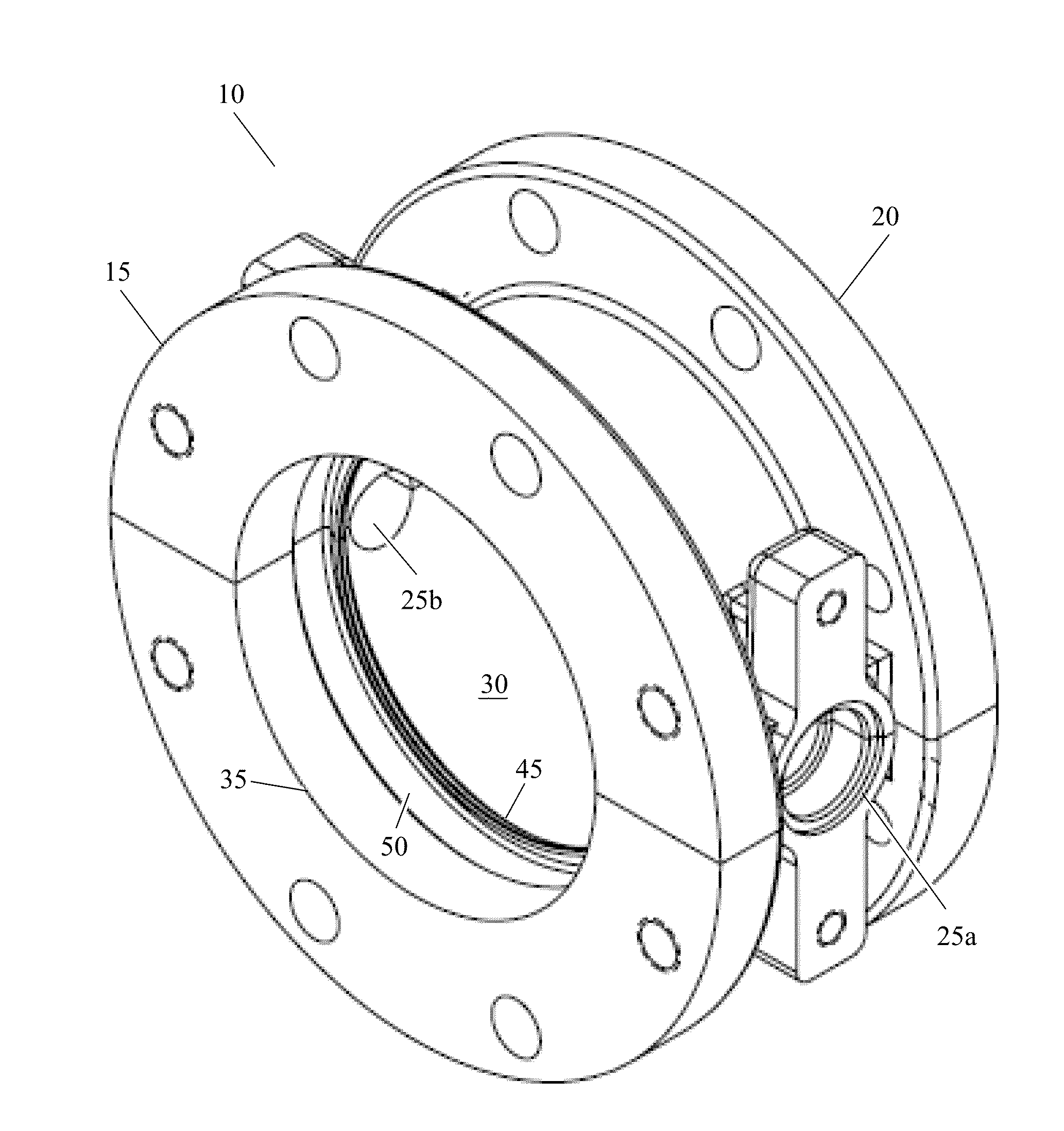
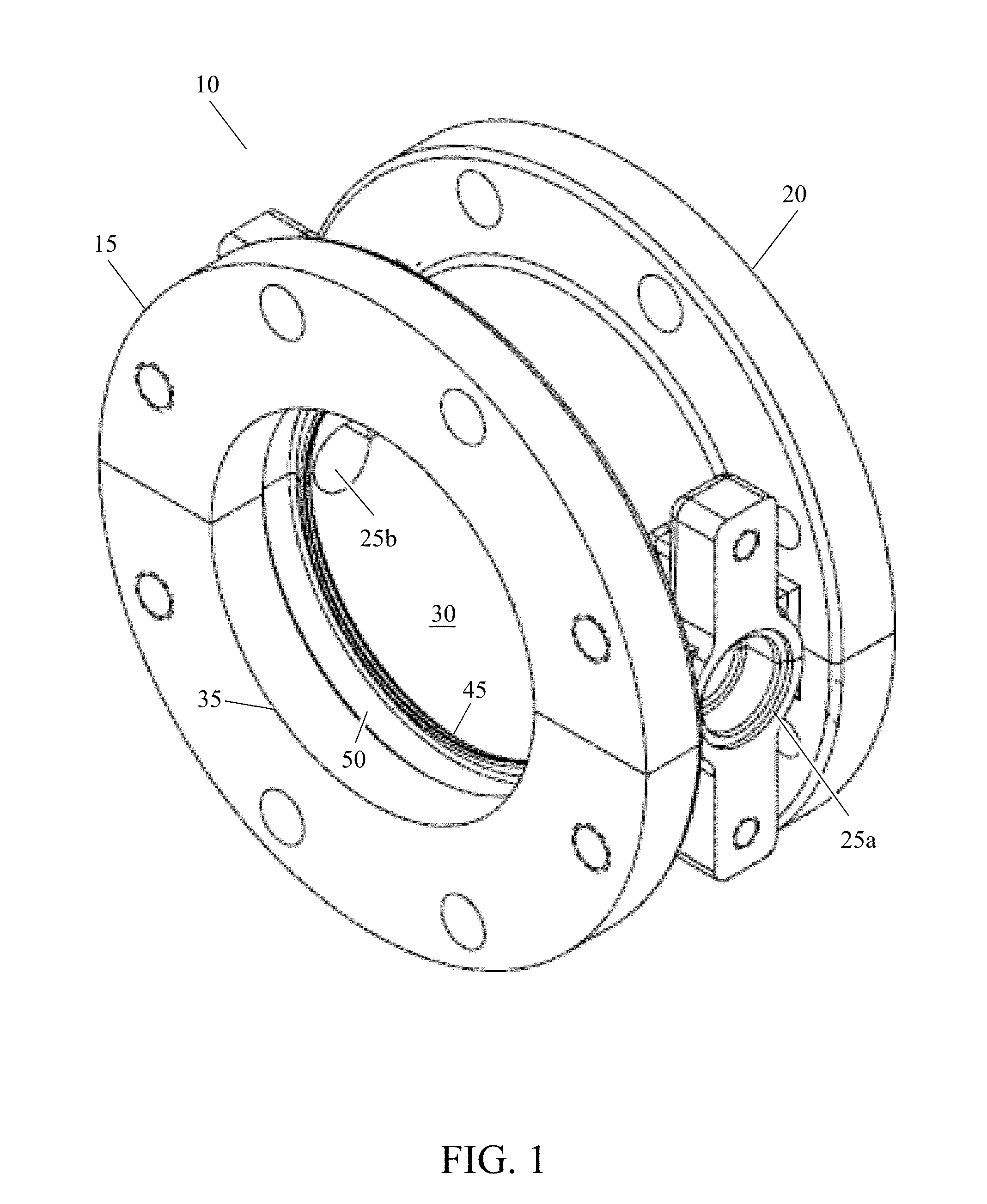
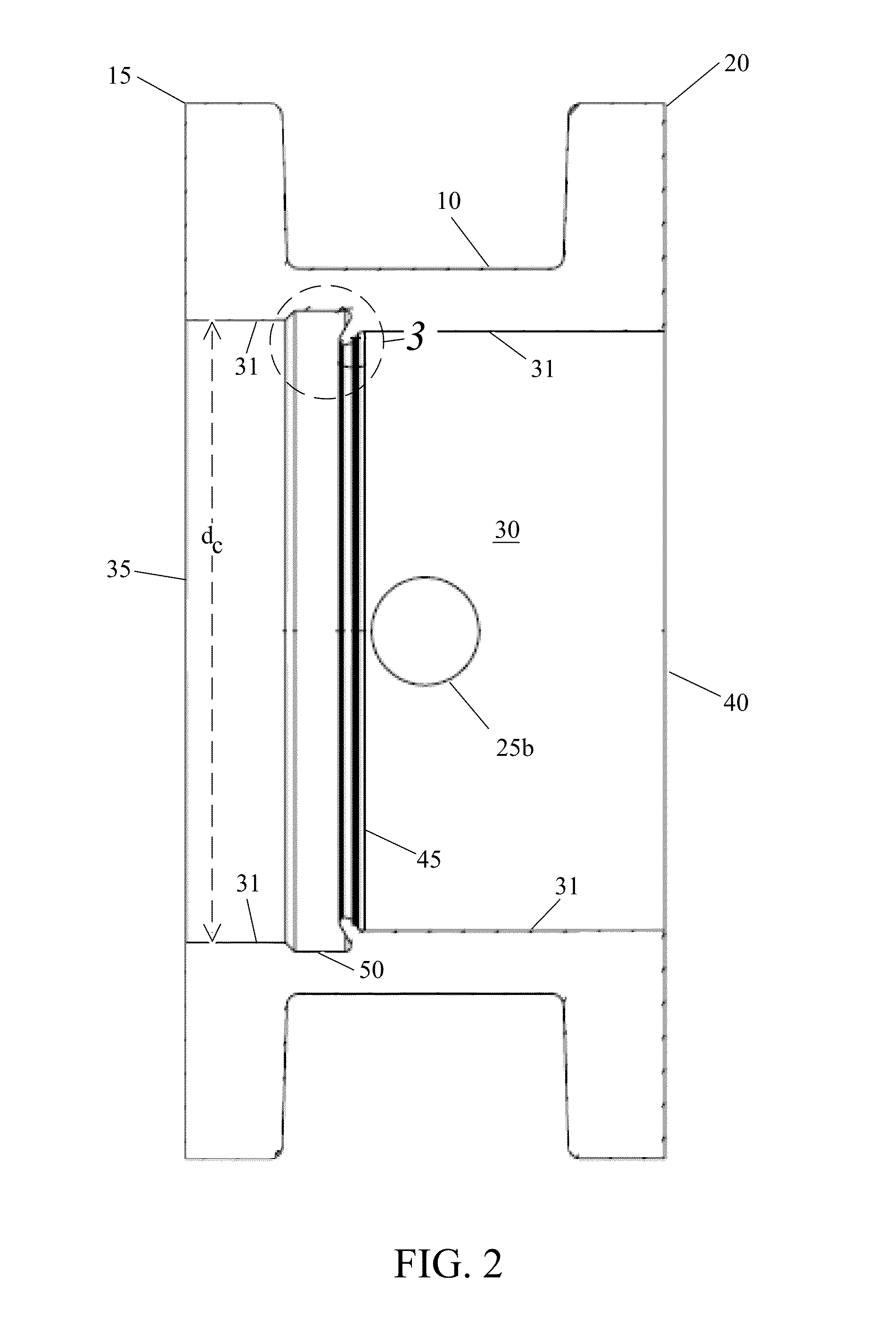
[0035]FIG. 1 shows a hollow valve body 10 of a butterfly valve. The hollow valve body 10 has a first end with an inlet 35, and an inlet flange 15 surrounding the inlet 35 for attachment to a piping system. A second end of the hollow valve body 10 has an outlet, and an outlet flange 20 for attachment to a piping system. A cylindrical flow channe...


PUM

PropertyMeasurementUnit
Lengthaaaaaaaaaa
Circumferenceaaaaaaaaaa

Abstract

A butterfly valve seal arrangement in a butterfly valve having a cylindrical flow channel with a wall includes a seal flange, an elastomeric seal, a seal channel, and an annular seal retaining ring. The seal flange extends into the cylindrical flow channel from the wall of the cylindrical flow channel. The seal channel is recessed into the wall of the cylindrical flow channel adjacent to the seal flange. And the annular seal retaining ring includes tabs extending into the seal channel which hold the annular seal retaining ring in the cylindrical flow channel. An elastomeric seal is held in compression in the seal channel and against the seal flange by the annular seal retaining ring, and extends into the cylindrical flow channel forming a seal surface held in compression against a vane seat of a vane in a position perpendicular to a direction of flow.

Description

BACKGROUND OF THE INVENTION[0001]1. Field of the Invention[0002]The invention pertains to the field of butterfly valve seals. More particularly, the invention pertains to mechanically retained butterfly valve seals.[0003]2. Description of Related Art[0004]Butterfly valves generally include a hollow valve body with an inlet and an outlet, and cylindrical flow channel passing between the inlet and the outlet. A vane is rotatably mounted between the inlet and the outlet on an operating stem passing laterally through the hollow valve body. When the operating stem is rotated, the vane may be rotated between a first position perpendicular to a flow direction between the inlet and the outlet, and a second position parallel to the flow direction. An annular elastomeric seal mounted circumferentially in the cylindrical flow channel at the location of the vane mates with a seat ring on the vane when the vane is in the first position, creating a fluid tight seal between the vane and the cylind...

Claims


Application Information

Patent Timeline
IPC IPC(8): F16K1/226F16J15/18
CPCF16J15/181F16K1/226F16K1/2263F16K1/2265F16K1/2266F16K1/2057
Inventor KENNEDY, PAUL
Owner KENNEDY VALVE
Features
  • Generate Ideas
  • Intellectual Property
  • Life Sciences
  • Materials
  • Tech Scout
  • Unparalleled Data Quality
  • Higher Quality Content
  • 60% Fewer Hallucinations
Learn More