System of illuminating poured surfaces

Inactive Publication Date: 2016-07-21
HELMSWORTH THOMAS
View PDF1 Cites 1 Cited by
  • Summary
  • Abstract
  • Description
  • Claims
  • Application Information

AI Technical Summary

Benefits of technology

The present invention is about a system for creating a pattern of light emitting from a poured surface. The system includes guide posts joined to the surface, a position sleeve removably attached to each guide post, and an optic fiber extending through the guide posts and position sleeves. The system can create a pattern of light at a desired location on the surface. The technical effects of the invention include accurate placement of light emitted from a poured surface, and improved control over the pattern of light.

Problems solved by technology

Current systems for providing illumination of walkways often supply more light than needed and so washout or otherwise detract from the scenery around the walkway, frustrating the lighting's aesthetic purpose or even causing night blindness.
Embedding fiber optics in the walkway is currently available though only in prefabricated components with embedded fiber optics, which can be prohibitively expensive and preclude a user from designing their own desired point of light pattern.
When installing the optic fibers into poured surfaces, however, the fibers tend to get bent over and displaced under the pour flow of the pre-hardened, viscous cementitious material.
As a result, someone currently desiring to create their own light pattern within a poured surface would not only have to place each optic fiber by hand, but would have difficulty even finding the optic fibers after the initial pour of the pre-hardened, viscous cementitious material.

Method used


Image

  • System of illuminating poured surfaces
  • System of illuminating poured surfaces
  • System of illuminating poured surfaces

Examples


Embodiment Construction

[0019]The following detailed description is of the best currently contemplated modes of carrying out exemplary embodiments of the invention. The description is not to be taken in a limiting sense, but is made merely for the purpose of illustrating the general principles of the invention, since the scope of the invention is best defined by the appended claims.

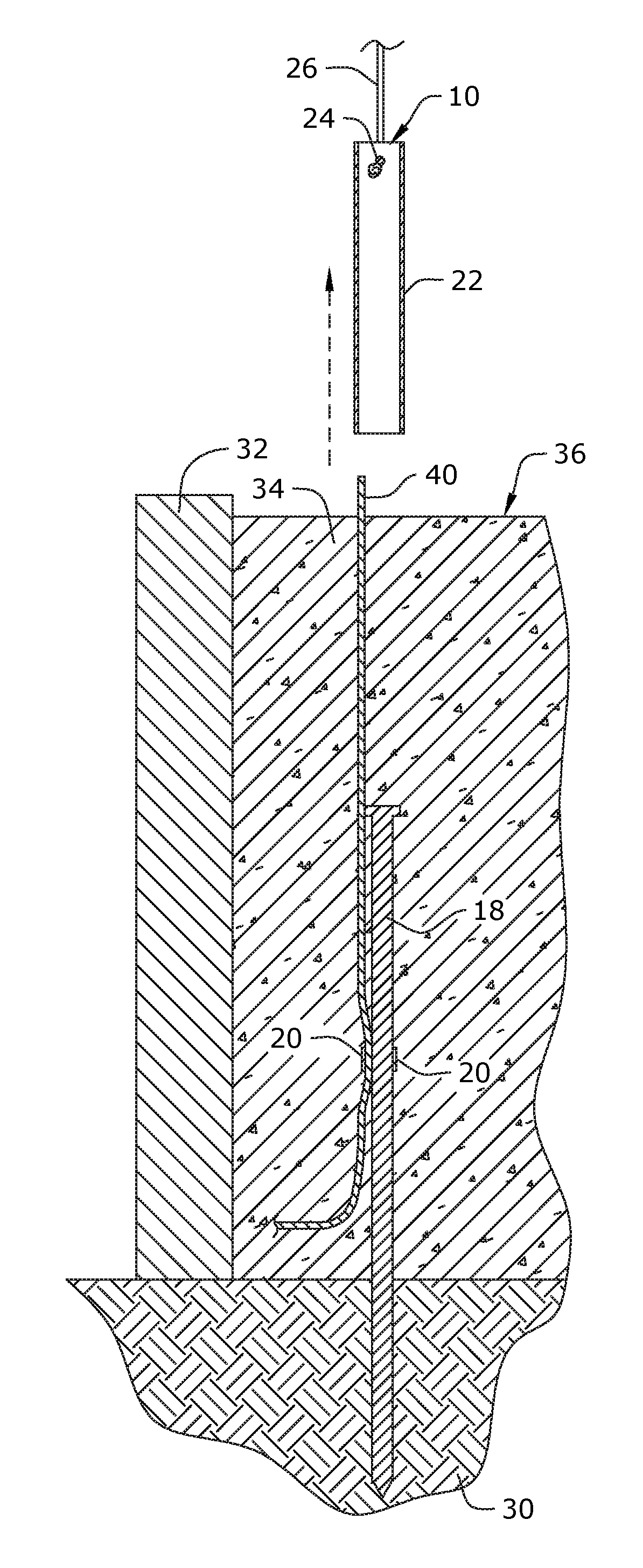
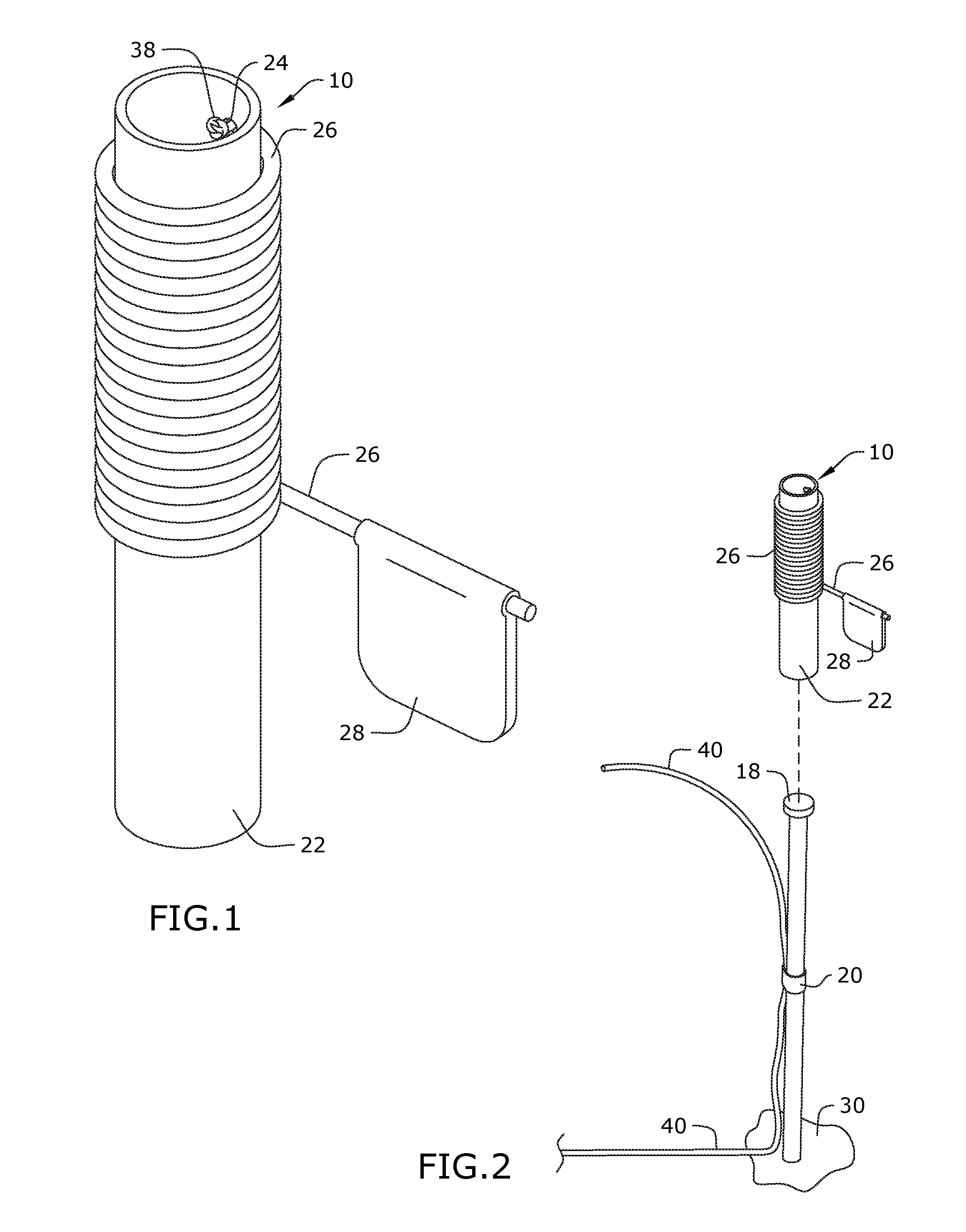
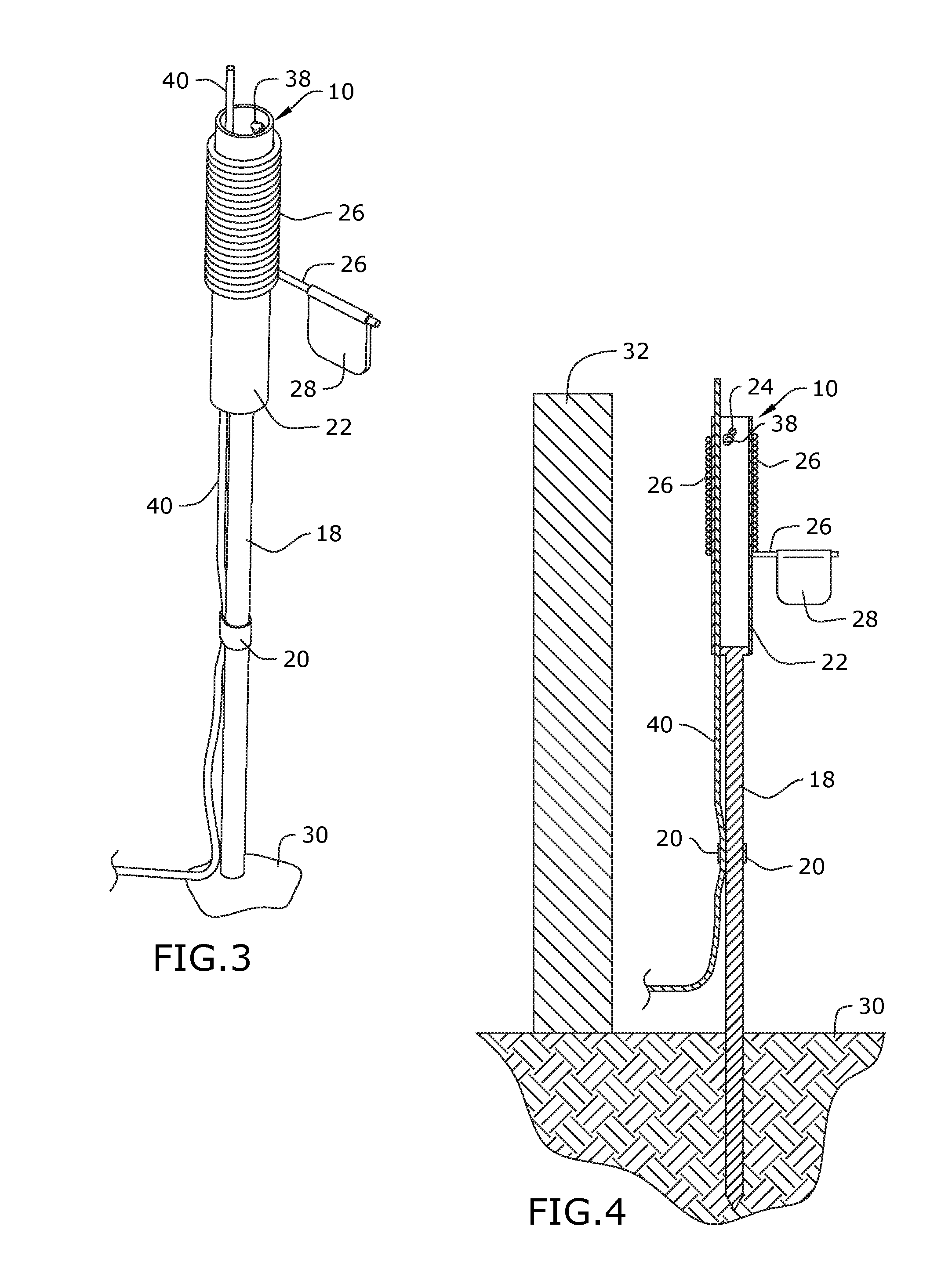
[0020]Broadly, an embodiment of the present invention provides a system for forming poured surfaces wherein embedding optic fibers produce a desired point of light pattern along the top of the poured surface. The system incorporates a guide post and coupled positioning apparatus adapted to support each optic fiber prior to and during the pouring and setting of the poured surface so that the optic fibers protrude above the top surface after setting, to be cut flush, forming the desired pattern of points of light. The present invention may include a system for illuminating poured surfaces 34 with user-determined point of light pat...


PUM


Abstract

A system for forming poured surfaces having a desired point of light patterns emitting from the top surface thereof is provided. The system retains the optic fibers along the desired point of light pattern through the pouring of the poured surface. The system incorporates a guide post and coupled positioning apparatus adapted to support each optic fiber prior to and during the pouring and setting of the poured surface so that the optic fibers protrude above the top surface after setting, to be cut flush, forming the desired pattern of points of light.

Description

CROSS-REFERENCE TO RELATED APPLICATION[0001]This application is a continuation-in-part of the U.S. non-provisional application Ser. No. 14 / 481,159, filed Sep. 9, 2014, the contents of which are herein incorporated by reference.BACKGROUND OF THE INVENTION[0002]The present invention relates to lighting systems and, more particularly, to a system for illuminating poured surfaces through adaptable point of light patterns.[0003]Current systems for providing illumination of walkways often supply more light than needed and so washout or otherwise detract from the scenery around the walkway, frustrating the lighting's aesthetic purpose or even causing night blindness. Embedding fiber optics in the walkway is currently available though only in prefabricated components with embedded fiber optics, which can be prohibitively expensive and preclude a user from designing their own desired point of light pattern.[0004]As can be seen, there is a need for a system for installing fiber optic illumina...

Claims


Application Information

Patent Timeline
IPC IPC(8): F21S8/02E01C17/00F21V8/00
CPCF21S8/022F21W2111/023E01C17/00G02B6/0008F21V33/006F21V2200/13G02B6/504
Inventor HELMSWORTH, THOMAS
Owner HELMSWORTH THOMAS
Why Eureka
Try Eureka