Modular distractor system for use in surgery

a technology of distractors and modules, applied in the field of ankle distraction procedures, can solve problems such as affecting the circumferential access of patients' feet and ankles

Active Publication Date: 2016-08-11
INNOVATIVE MEDICAL PRODS
View PDF5 Cites 6 Cited by
  • Summary
  • Abstract
  • Description
  • Claims
  • Application Information

AI Technical Summary

Problems solved by technology

The use of such equipment in the vicinity of the ankle could impair circumferential access to the patient's foot and ankle, during surgery, under some circumstances.

Method used


Image

  • Modular distractor system for use in surgery
  • Modular distractor system for use in surgery
  • Modular distractor system for use in surgery

Examples


Embodiment Construction

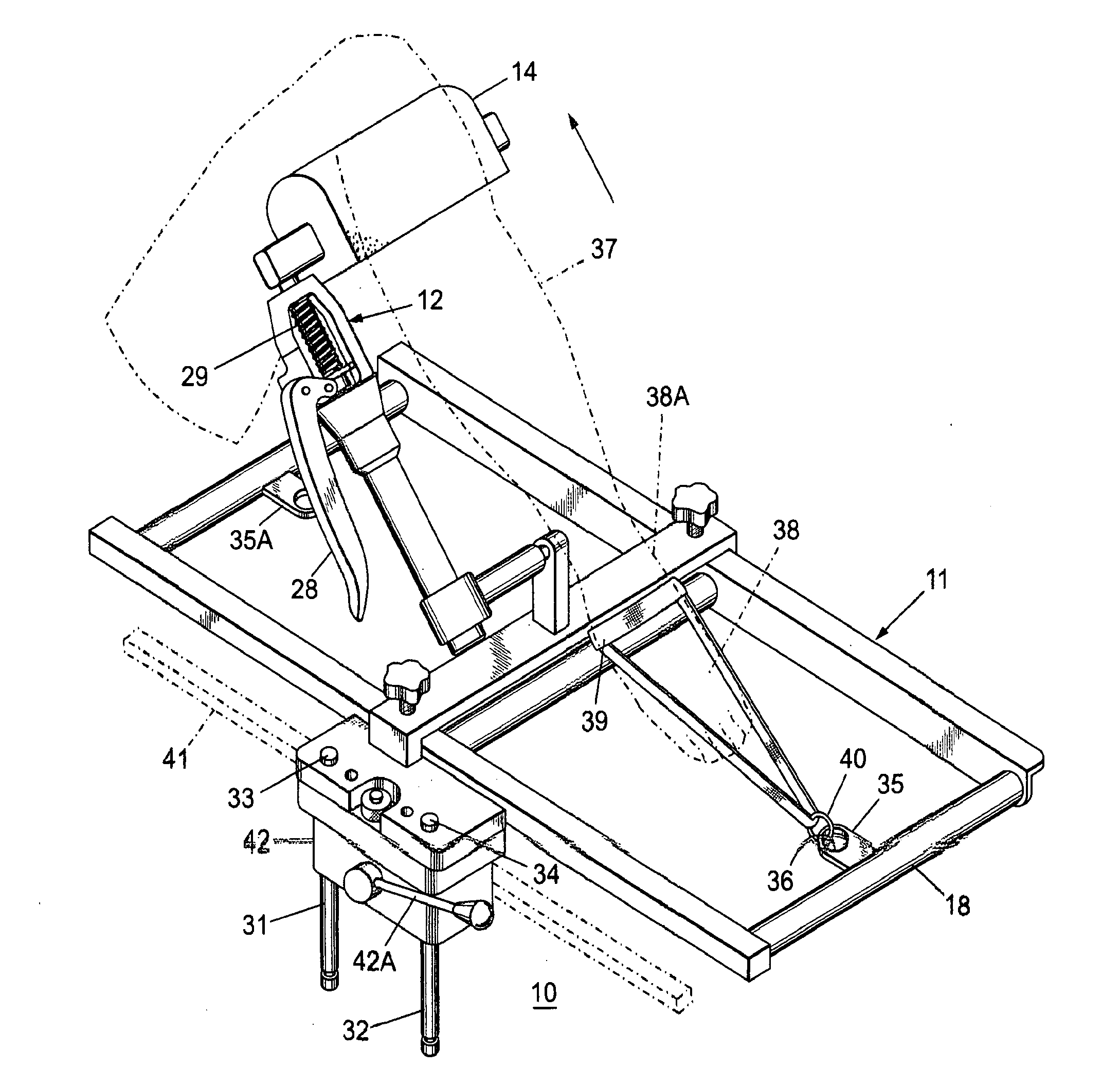
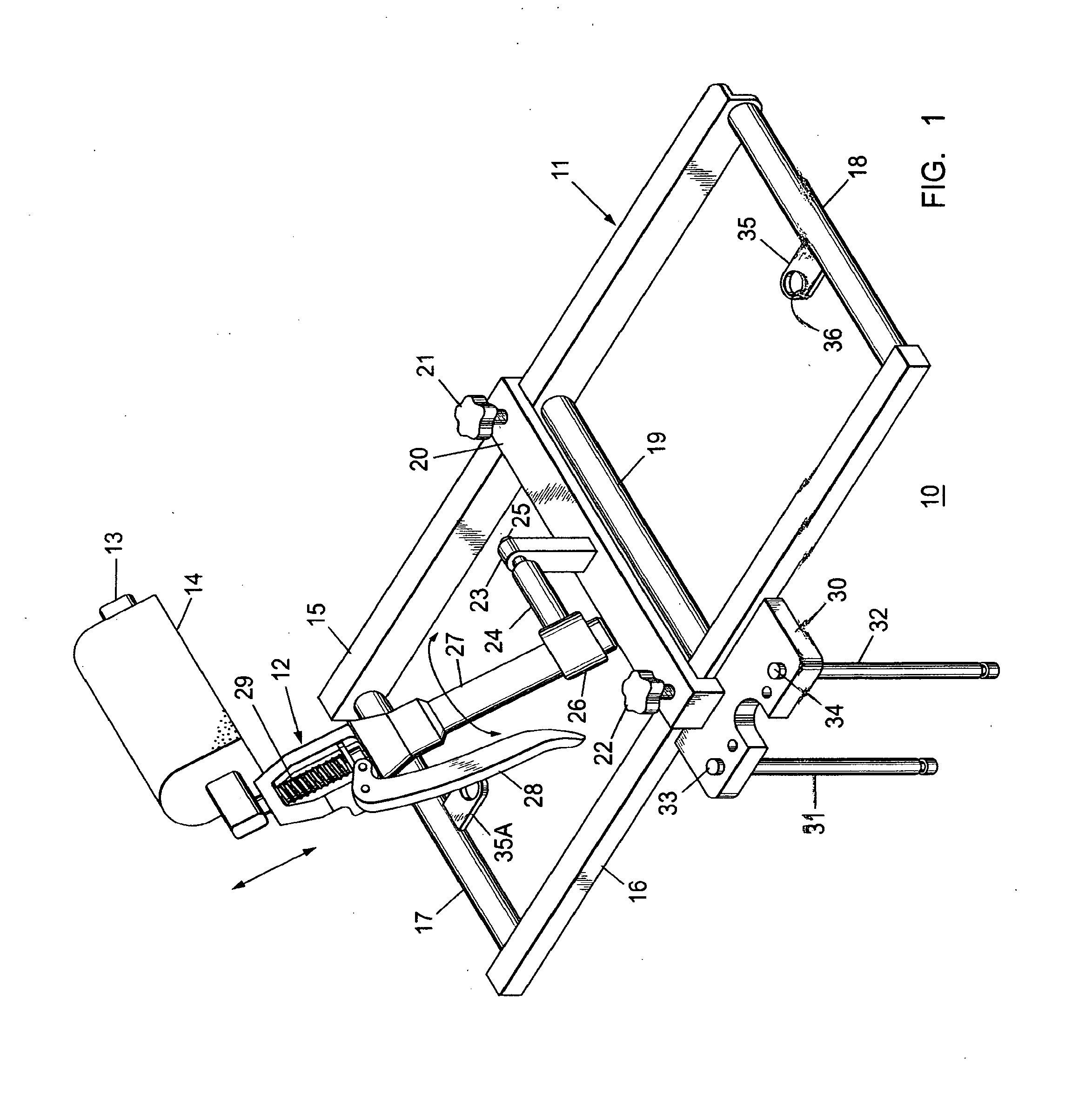
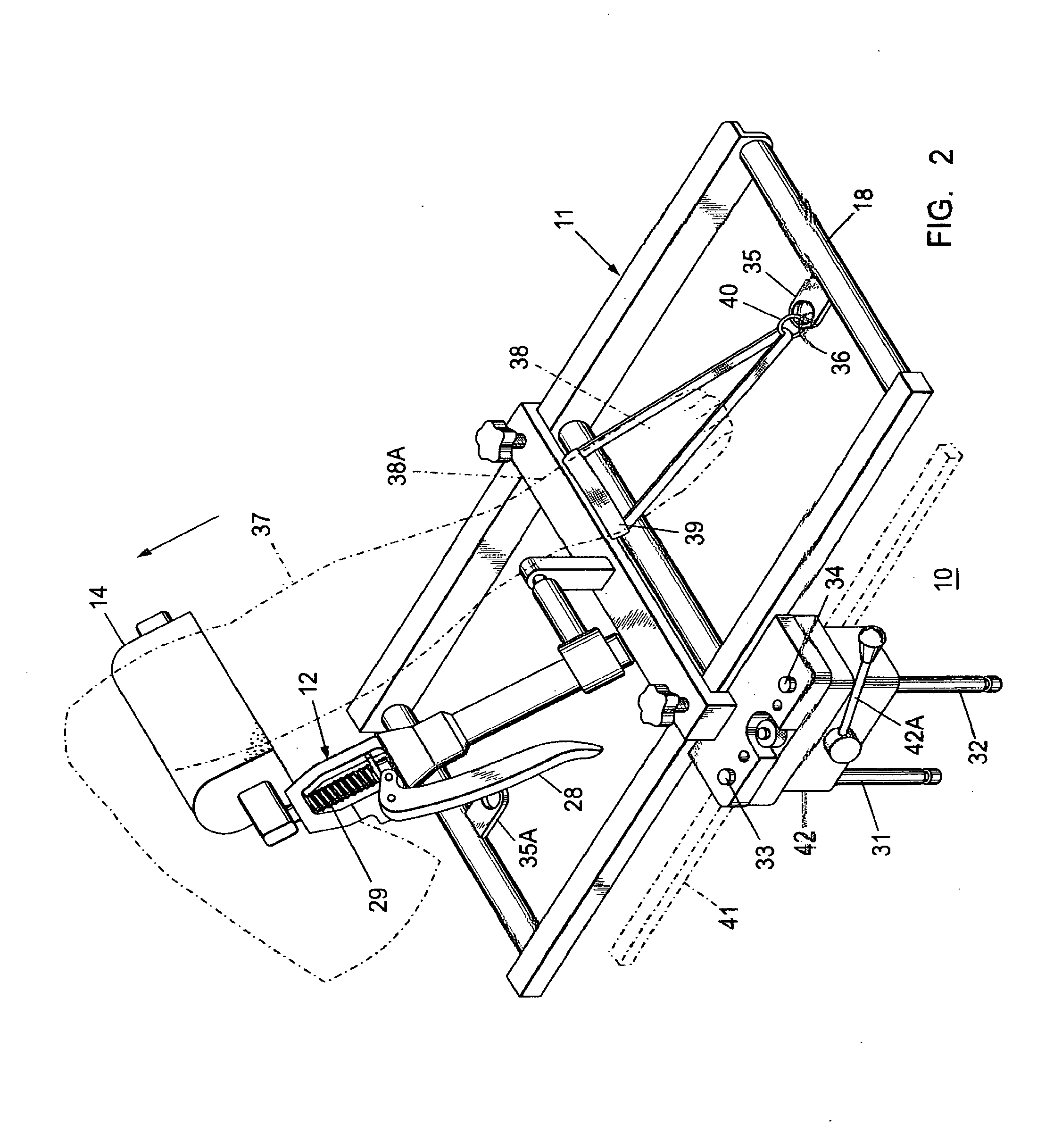
[0013]Non-limiting embodiments of the present invention will be described below with reference to the accompanying drawings, wherein like reference numerals represent like elements throughout. While the invention has been described in detail with respect to the preferred embodiments thereof, it will be appreciated that upon reading and understanding of the foregoing, certain variations to the preferred embodiments will become apparent, which variations are nonetheless within the spirit and scope of the invention.

[0014]The terms “a” or “an”, as used herein, are defined as one or as more than one. The term “plurality”, as used herein, is defined as two or as more than two. The term “another”, as used herein, is defined as at least a second or more. The terms “including” and / or “having”, as used herein, are defined as comprising (i.e., open language). The term “coupled”, as used herein, is defined as connected, although not necessarily directly, and not necessarily mechanically.

[0015]R...


PUM


Abstract

A manual distractor unit is mounted upon a support frame attached to an operating table side rail. An ankle strap is attached to the support frame and to the patient's ankle. A patient's knee support pad, extending from the distractor unit, is positioned under the patient's knee to provide traction to the patient's limb at the ankle, which is secured to the support frame by the ankle strap.

Description

CROSS-REFERENCE TO RELATED APPLICATION[0001]This application is a continuation of and claims the benefit of U.S. patent application Ser. No. 13 / 134,238 filed Jun. 3, 2011 entitled “Modular distractor for use in ankle surgery” which is incorporated by reference herein in its entirety. The patent application identified above is incorporated here by reference in its entirety to provide continuity of disclosure.FIELD OF THE INVENTION[0002]The present invention relates to ankle distraction procedures and, more particularly, to an apparatus, system and method for distracting an ankle and / or leg at a knee to provide improved access to the ankle area and lower leg.BACKGROUND OF THE INVENTION[0003]Methods currently available for ankle distraction procedures generally restrain the patient's leg and apply controlled pressure to the ankle for the required traction.[0004]U.S. Pat. No. 5,290,220 entitled “Non-Invasive Distraction System for Ankle Arthroscopy” and U.S. Pat. No. 5,025,802 entitled ...

Claims


Application Information

Patent Timeline
Patent Type & Authority Applications(United States)
IPC IPC(8): A61B17/02A61B17/66
CPCA61B2017/681A61B17/60A61B17/66A61B17/025A61G13/1245A61F5/04A61G13/0036A61G13/101A61G13/12
Inventor DEMAYO, EDWARD
Owner INNOVATIVE MEDICAL PRODS
Why Eureka
Try Eureka