
Aircraft capable of vertical takeoff

a technology of vertical takeoff and aircraft, applied in vertical landing/takeoff aircraft, vehicles, power plants, etc., can solve the problems of high efficiency and low imbalance, and achieve high travel flight speed and good hovering characteristics

Active Publication Date: 2016-08-18
AIRBUS DEFENCE & SPACE
View PDF36 Cites 81 Cited by
  • Summary
  • Abstract
  • Description
  • Claims
  • Application Information

AI Technical Summary

Benefits of technology

The present invention aims to provide an aircraft that can both well hover and quickly travel at high speeds.

Problems solved by technology

Such a propeller has, on the one hand, a high degree of efficiency and, on the other hand, low imbalance.

Method used


Image

  • Aircraft capable of vertical takeoff
  • Aircraft capable of vertical takeoff
  • Aircraft capable of vertical takeoff

Examples


Embodiment Construction

[0049]The following detailed description makes reference to the accompanying drawings, which, for illustration, show specific details and specific embodiments in which the present invention can be realized.

[0050]Herein, the word “exemplary” is used to mean “serving as an example, case, or illustration.” Each specific embodiment or realization described herein as “exemplary” is not necessarily to be interpreted as preferred or advantageous relative to other specific embodiments or realizations.

[0051]In the following detailed description, reference is made to the accompanying drawings, which form a part thereof and in which, for illustration, particular specific embodiments are shown in which the present invention can be realized. In this respect, directional terminology, such as “above,”“below,”“at front,”“at rear,”“front,”“rear,” etc., is used with reference to the orientation of the described Figure(s). Because components of exemplary embodiments can be positioned in a number of di...


PUM


Abstract

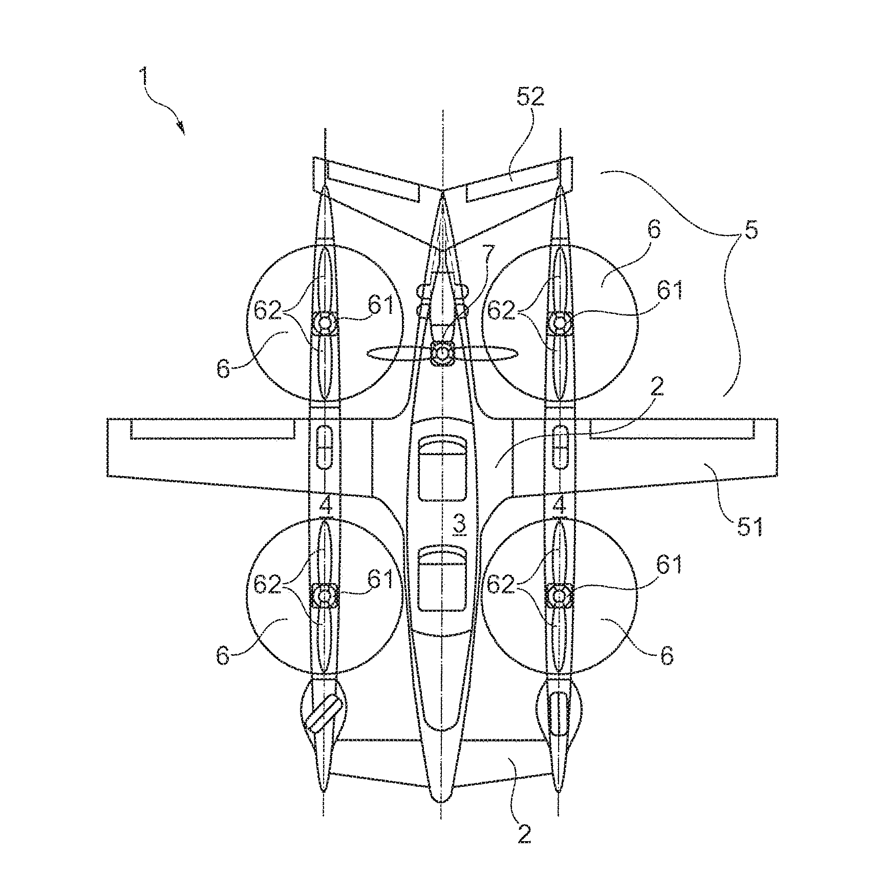
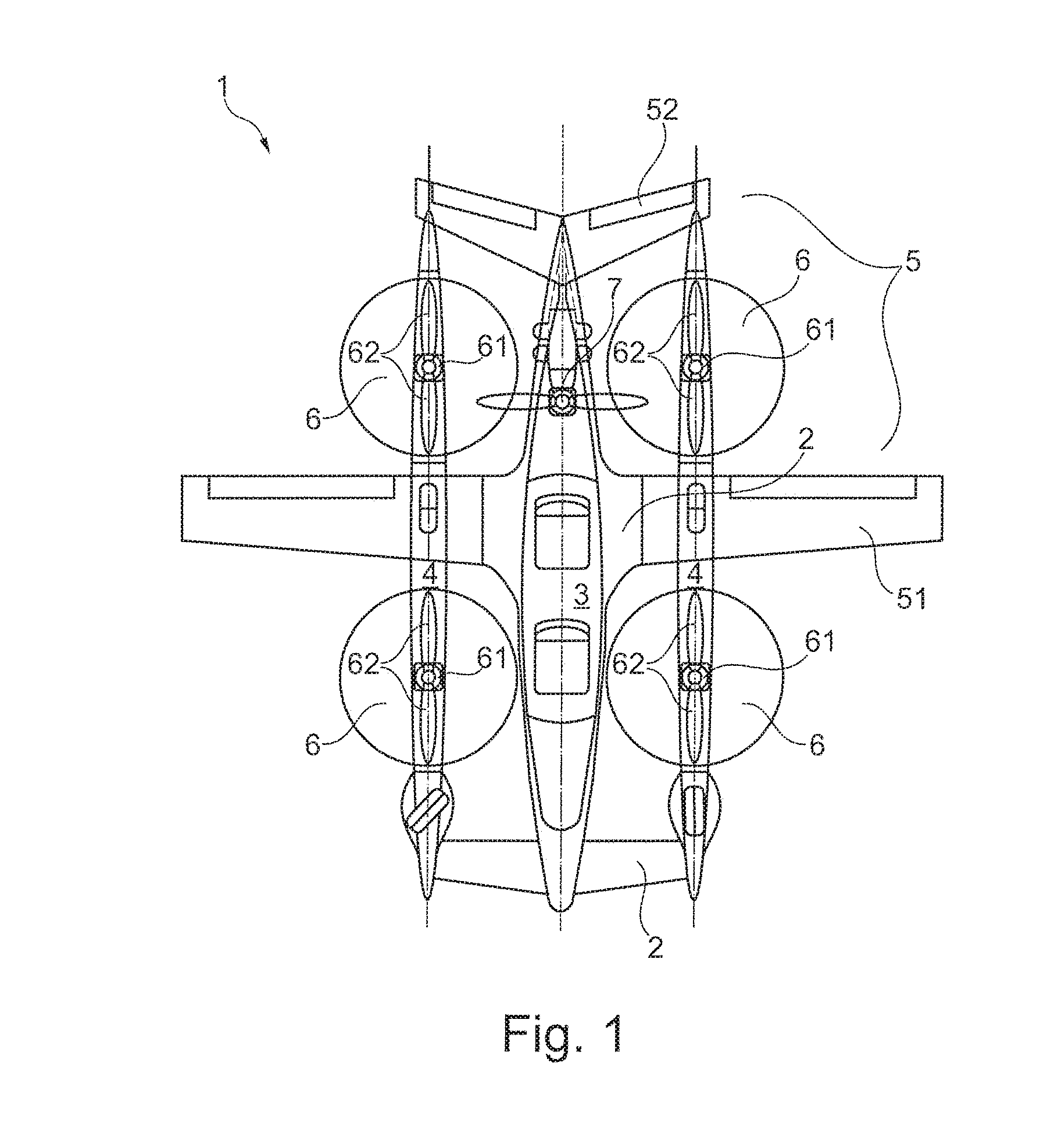
An aircraft has a bearing structure, the bearing structure having at least one central fuselage and two pylons each situated at a distance laterally from the fuselage. In addition, the aircraft has a wing structure, at least four hub rotors, and at least one thrust drive. Each hub rotor is fastened to the bearing structure, has a propeller having two propeller blades, and produces, through rotation of the propeller, an upward drive force acting in the vertical direction on the aircraft. The thrust drive is produces a thrust force acting in the horizontal direction on the bearing structure. The pylons each have two hub rotors, the hub rotors being configured to arrest respective propeller blades of a hub rotor in a position relative to the pylons. In the arrested position, the propeller blades of a hub rotor do not extend beyond the outer dimensions of the pylons.

Description

CROSS-REFERENCES TO RELATED APPLICATIONS[0001]This application claims the benefit of the German patent application No. 10 2015 001 704.7 filed on Feb. 13, 2015, the entire disclosures of which are incorporated herein by way of reference.BACKGROUND OF THE INVENTION[0002]The present invention relates to an aircraft capable of vertical takeoff, similar for example to a quadcopter.[0003]For many applications, it is desirable to have available an aircraft that can take off from a minimally small surface and thus, for example, does not require any special large-area airport. In addition, for some purposes an aircraft is required that is agile and that can be maneuvered precisely, and that preferably can hover in place with good hovering characteristics.[0004]For example, for air monitoring and reconnaissance aircraft are used that are intended to hover over a target of interest, while, for example, being capable of recording images from the air. In an alternative application, an aircraft ...

Claims


Application Information

Patent Timeline
Patent Type & Authority Applications(United States)
IPC IPC(8): B64C29/00B64D27/02B64D27/24
CPCB64C27/30B64C29/0025B64C2201/108B64D2027/026B64D27/02B64D27/24B64C2201/165B64C27/24B64C27/28B64C27/32B64C27/46B64C29/00B64U50/13B64D27/026B64U10/20B64U20/70B64U30/10B64U50/33
Inventor NIEDZBALLA, HANS
Owner AIRBUS DEFENCE & SPACE
Learn More