Multiple Position Locking Handle For An Exercise Machine

a multi-position locking and exercise machine technology, applied in the direction of gymnastic exercise, frictional force resistor, sport apparatus, etc., can solve the problems of handle rotation or other unexpected movement, handle grabbing may not affirmatively,

Active Publication Date: 2016-09-08
LAGREE TECH INC
View PDF5 Cites 85 Cited by
  • Summary
  • Abstract
  • Description
  • Claims
  • Application Information

AI Technical Summary

Problems solved by technology

One potential problem with some adjustable grab handle mechanisms is that the grab handles may not affirmatively lock into a new position after adjustment.
In the event an exerciser inadvertently pulls up on the handle during an exercise, the lifted handle may accidentally disengage the handle thereby allowing the handle to rotate or otherwise move unexpectedly.

Method used


Image

  • Multiple Position Locking Handle For An Exercise Machine
  • Multiple Position Locking Handle For An Exercise Machine
  • Multiple Position Locking Handle For An Exercise Machine

Examples


Embodiment Construction

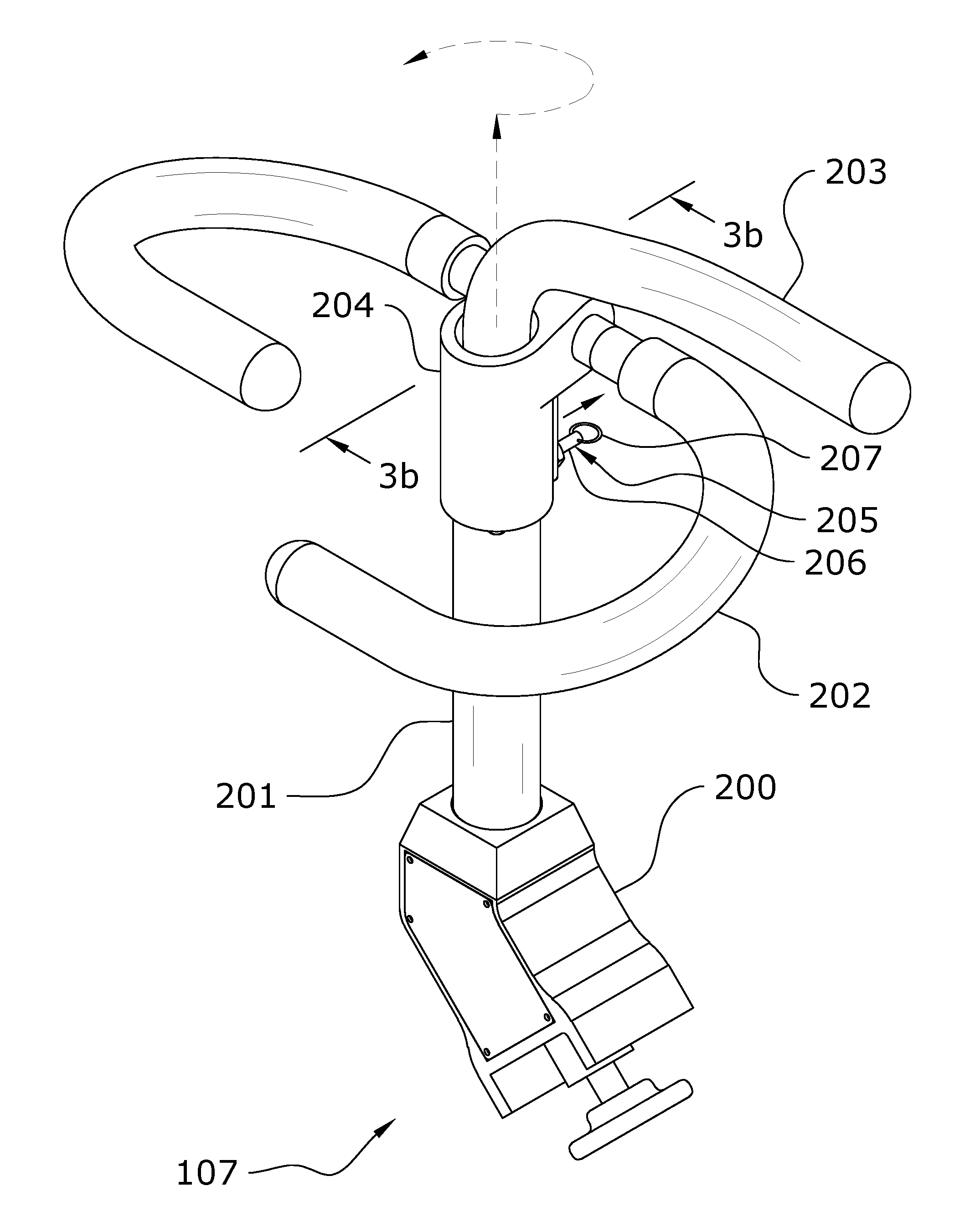
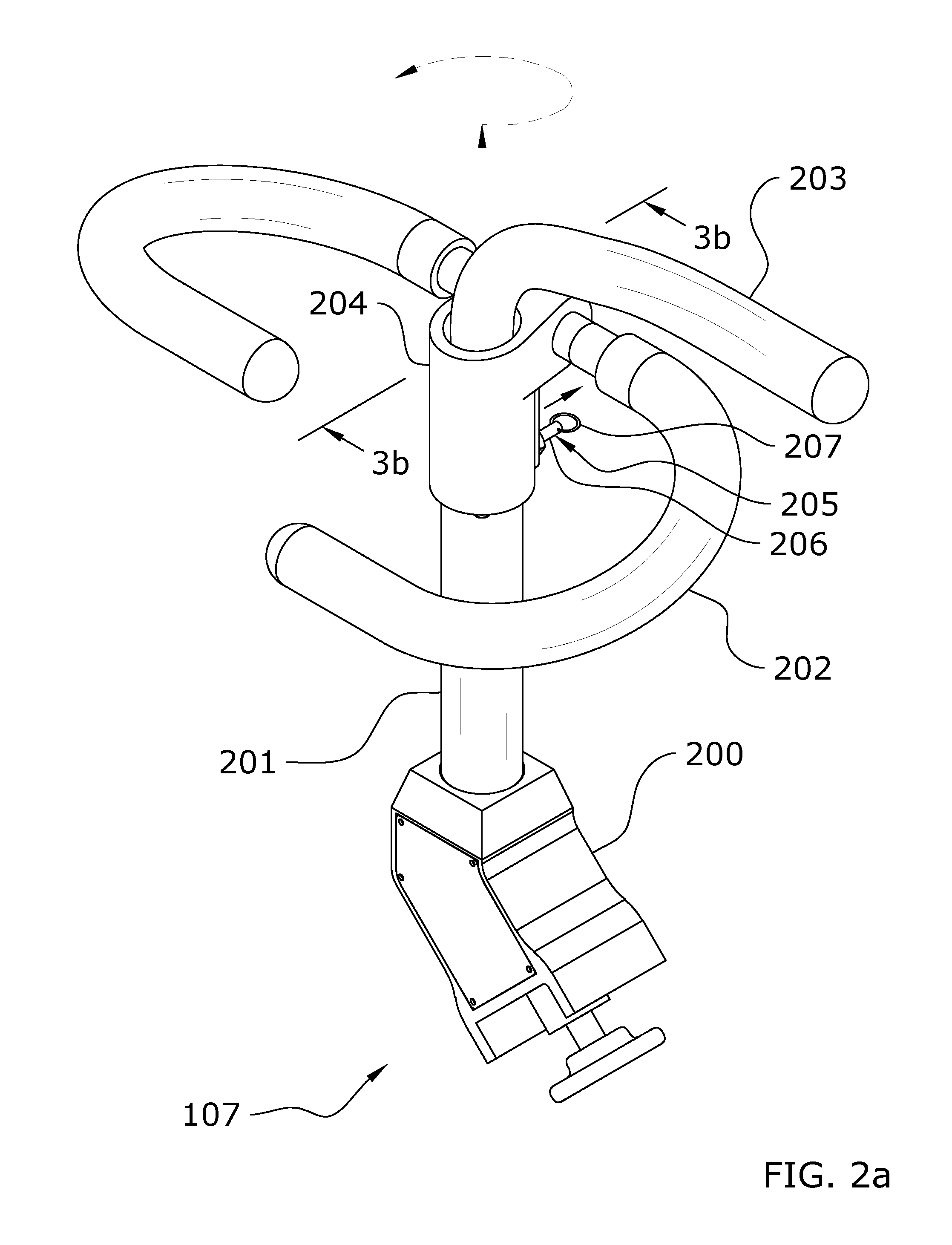
[0036]An example multiple position locking handle for an exercise machine generally comprises a tubular base having a lower end and an upper end, an elongated member extending through the opening of the upper end of the tubular base and extending downwardly through at least a portion of the tubular base, a handle extending outwardly from the elongated member at an angle, and a locking device. The elongated member is movable within the tubular base when the locking device is in the unlocked state and is substantially not movable within the tubular base when the locking device is in the locked state.

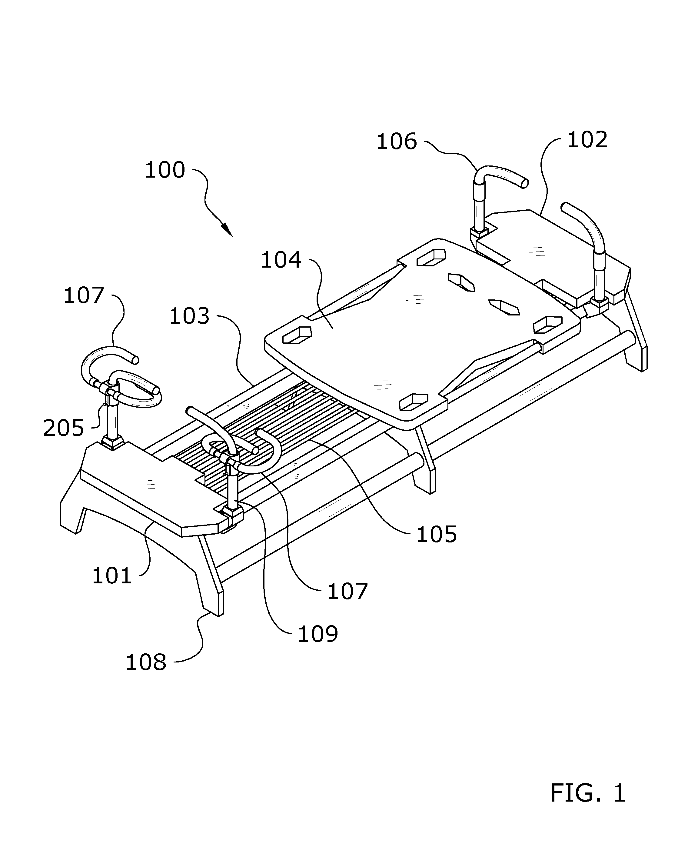
[0037]“Pilates apparatus” as used herein may also include “machine”, “exercise apparatus”, or “exercise machine” with no difference in meaning or intention as the descriptions are interchangeable. U.S. Pat. Nos. 7,803,095 and 8,641,585 illustrate exemplary exercise machines comprised of a “Pilates apparatus” and are hereby incorporated by reference herein.

[0038]FIG. 1 is an exemplary diagr...


PUM


Abstract

A multiple position locking handle for an exercise machine for that is movable into a plurality of different positions when unlocked and that is retained in a single secure position when locked. The multiple position locking handle for an exercise machine generally includes a tubular base having a lower end and an upper end, an elongated member extending through the opening of the upper end of the tubular base and extending downwardly through at least a portion of the tubular base, a handle extending outwardly from the elongated member at an angle, and a locking device. The elongated member is movable within the tubular base when the locking device is in the unlocked state and is substantially not movable within the tubular base when the locking device is in the locked state.

Description

CROSS REFERENCE TO RELATED APPLICATIONS[0001]The present application is a continuation-in-part of U.S. application Ser. No. 14 / 841,210 filed on Aug. 31, 2015 (Docket No. LAGR-052), which is a continuation of U.S. application Ser. No. 13 / 924,088 filed on Jun. 21, 2013 now issued as U.S. Pat. No. 9,119,989 (Docket No. LAGR-003), which claims priority to U.S. Provisional Application No. 61 / 719,757 filed Oct. 29, 2012 (Docket No. LAGR-001). The present application also claims priority to U.S. Provisional Application No. 62 / 156,614 filed May 4, 2015 (Docket No. LAGR-047). Each of the aforementioned patent applications, and any applications related thereto, is herein incorporated by reference in their entirety.STATEMENT REGARDING FEDERALLY SPONSORED RESEARCH OR DEVELOPMENT[0002]Not applicable to this application.BACKGROUND[0003]1. Field[0004]Example embodiments in general relate to a multiple position locking handle for an exercise machine that is movable into a plurality of different pos...

Claims


Application Information

Patent Timeline
Patent Type & Authority Applications(United States)
IPC IPC(8): A63B21/00A63B21/012
CPCA63B21/0125A63B21/4035A63B21/00061A63B21/00065A63B21/023A63B21/0407A63B21/0428A63B21/4001A63B21/4029A63B21/4045A63B22/0046A63B22/0087A63B23/0211A63B23/1236A63B71/0054A63B2023/003A63B2208/0214A63B2225/09
Inventor LAGREE, SEBASTIEN ANTHONY LOUIS
Owner LAGREE TECH INC
Why Eureka
Try Eureka