Exercise Machine Rail System

a technology for exercise machines and rail systems, applied in gymnastic exercise, resilient force resistors,stilts, etc., can solve problems such as injury of exercisers, inadequate base structure, and legal claims against pilates studios

Active Publication Date: 2015-12-17
LAGREE TECH INC
View PDF47 Cites 113 Cited by
  • Summary
  • Abstract
  • Description
  • Claims
  • Application Information

AI Technical Summary

Benefits of technology

[0019]The invention generally relates to an exercise machine which includes either two rails in close relationship which are linked together via connectors or a singular rail. Bias members are disclosed as either extendin

Problems solved by technology

One major deficiency of contemporary Pilates apparatuses is a base structure of sufficient width and length to provide stability of the parallel rails and slidable carriage supported thereupon.
Therefore, there is an ever-present danger that the carriage will slide out from under exercisers any time they attempt to mount or dismount the apparatus, oftentimes resulting in exerciser injury and legal claims against the Pilates studio.
Another major deficiency of contemporary Pilates apparatuses is a rail configuration that creates additional points of apparatus contact by an exerciser that may result in injury.
At the foot end of the apparatus, the area defined as the lateral dimension between the parallel rails, and the longitudinal dimension between the slidable carriage and the stationary structure between which the springs are removably attached, create a “field of springs” that can routinely cause injury to exercisers who accidentally step or fall through the ex

Method used


Image

  • Exercise Machine Rail System
  • Exercise Machine Rail System
  • Exercise Machine Rail System

Examples


first embodiment

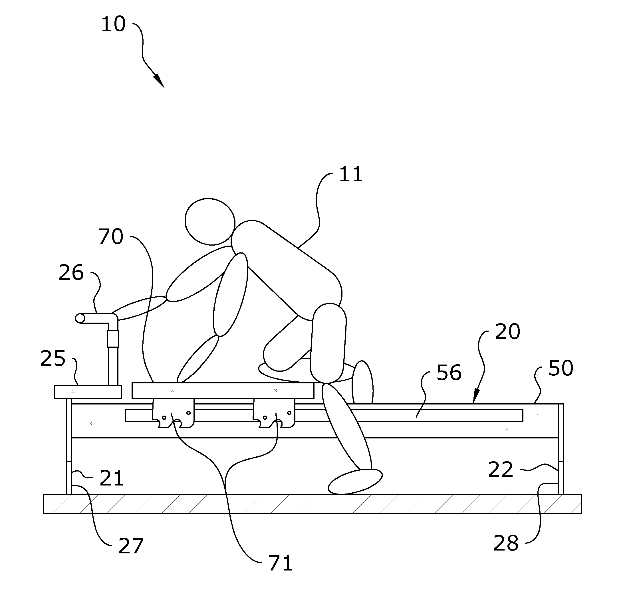
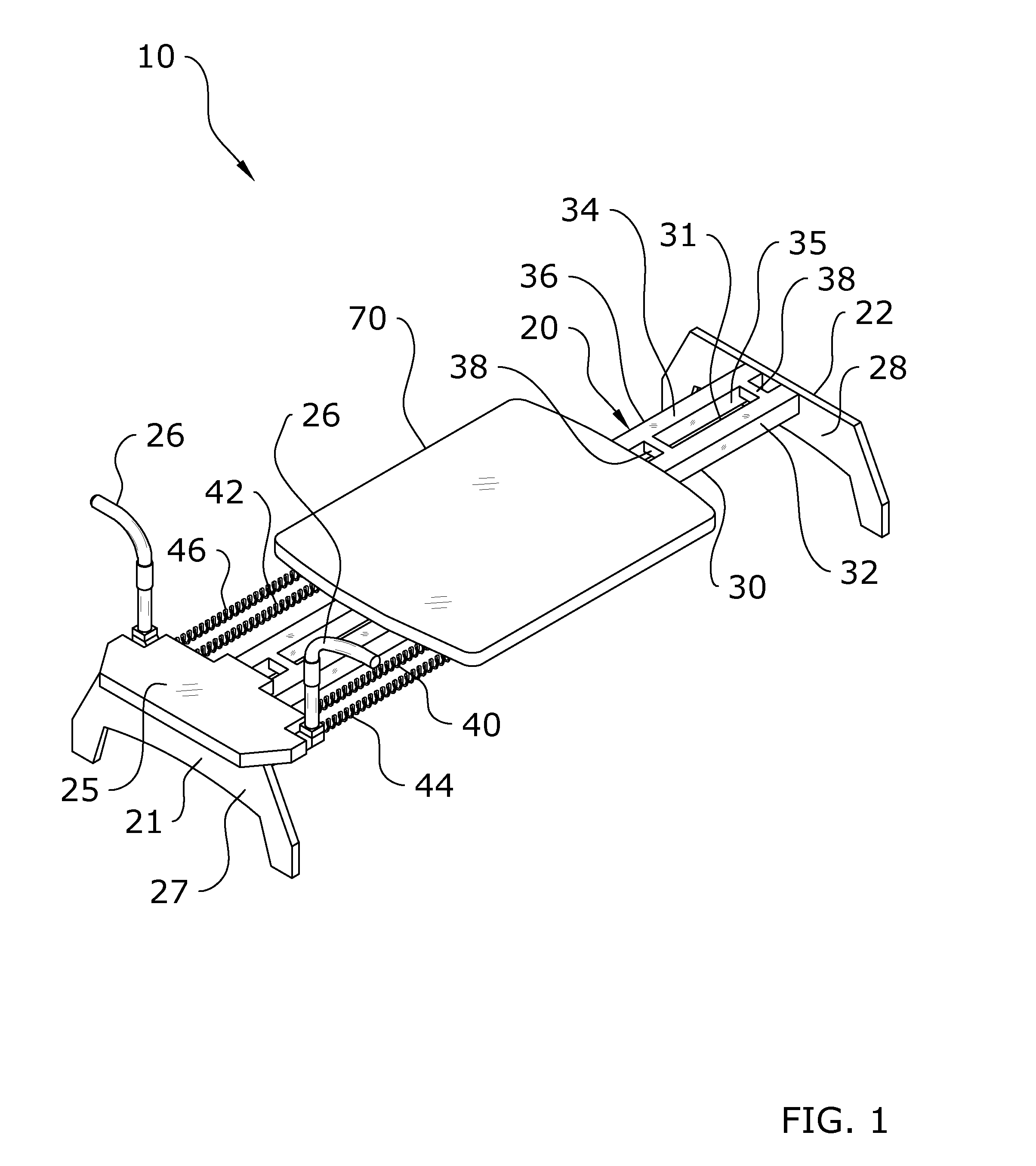
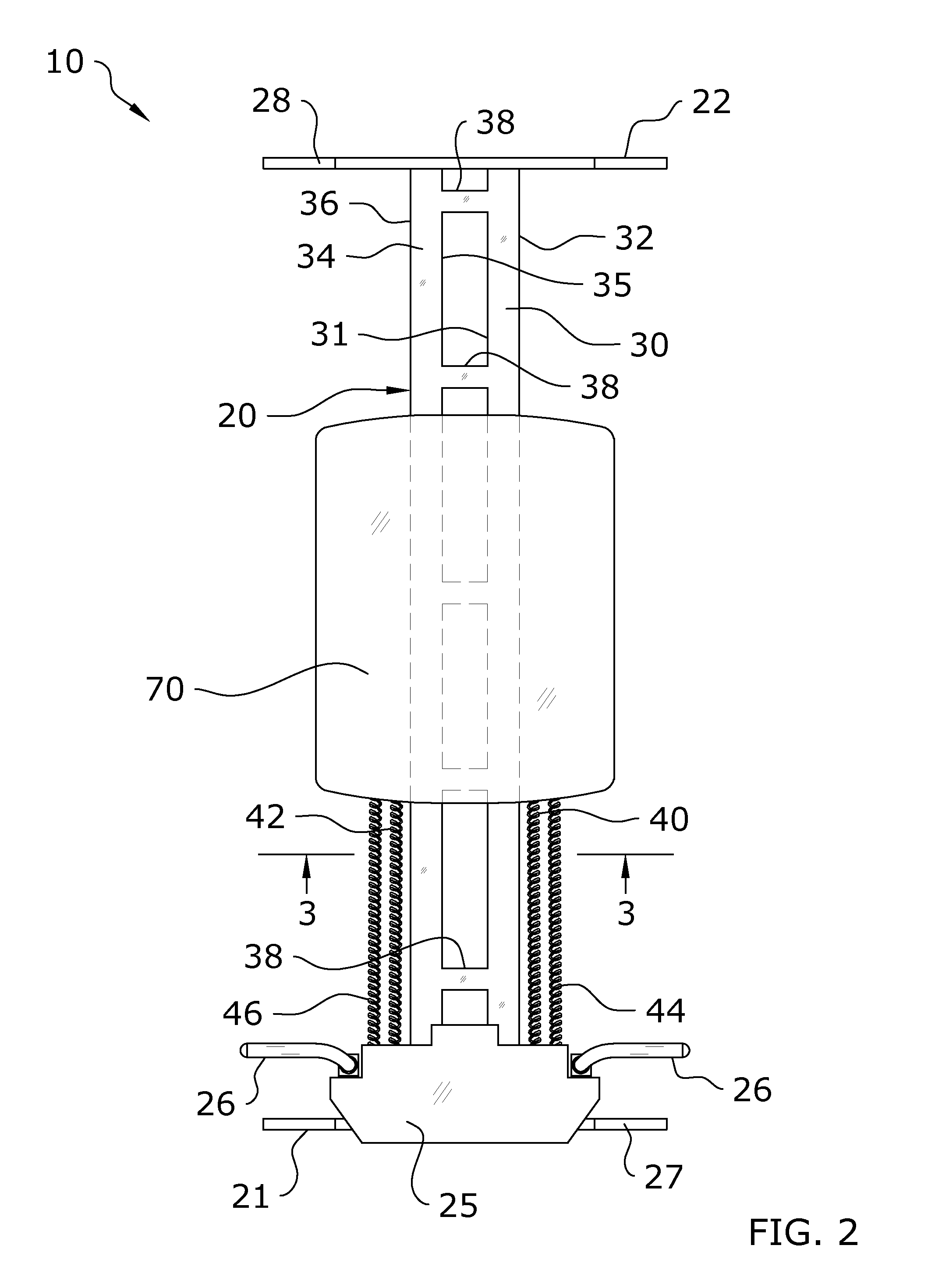
[0063]FIGS. 1-4 illustrate the present invention in which a pair of rails 30, 34 extend in close spaced-apart relationship with each other between the first end 21 and the second end 22 of the exercise machine 20. It is preferable that the rails 30, 34 be minimally spaced from each other so that, taken together, the pair of rails 30, 34 comprise a narrow structure which is easy to straddle or walk around for an exerciser 11. The carriage 70 is adapted to move, such as by sliding, along the pair of rails 30, 34 through various methods known in the art for moving a carriage 70 along rails 30, 34.

[0064]In the first embodiment of the present invention, the first rail 30 and second rail 34 extend parallel with respect to each other. The first rail 30 includes a first interior side 31 which faces toward the second rail 34 and a first exterior side 32 which faces away from the second rail 34. Similarly, the second rail 34 includes a second interior side 35 which faces toward the first rail...

second embodiment

[0072]FIGS. 5-10 illustrate the present invention which utilizes a single rail 50 which is centrally positioned along the longitudinal axis of the exercise machine 20 and bias members 40, 42, 44, 46 positioned laterally to the singular rail 50. The rail 50 extends between the first end 21 and the second end 22 of the exercise machine 20. The rail 50 includes an upper end 51, a lower end 52, a first side 53, and a second side 54.

[0073]The rail 50 may comprise various configurations, but will preferably comprise an I-shaped cross-section as shown in the figures, with the rail 50 comprising an I-beam. With such a configuration, the rail 50 includes a first channel 56 extending along its first side 53 and a second channel 57 extending along its second side 54.

[0074]The interconnection between the carriage 70 and the rail 50 is best shown in FIG. 8. Generally, one or more wheels 76, 77, 78, 79 will extend down from the carriage 70, such as by usage of a lower bracket 71, to engage with t...

third embodiment

[0085]FIGS. 11-14 illustrate the present invention which utilizes a single rail 50 which is centrally positioned along the longitudinal axis of the exercise machine 20 and bias members 40, 42, 44, 46 internally to the singular rail 50. The rail 50 extends between the first end 21 and the second end 22 of the exercise machine 20. The rail 50 includes an upper end 51, a lower end 52, a first side 53, and a second side 54. Additionally, in this embodiment, the rail 50 is substantially hollow with an internal channel 60 extending therethrough between its first and second ends 53, 54. The rail 50 may also include an upper slot 59 through which the lower bracket 71 will extend to link the carriage 70 with a bias mount 72 kept internal to the rail 50. In this embodiment of the present invention, the bias members 40, 42, 44, 46 extend through the internal channel 60 of the rail 50 as shown in FIG. 12.

[0086]As can be readily seen in the drawings, the internal channel 60 of the rail 50 furthe...


PUM


Abstract

An exercise machine rail system for improved exerciser mounting and dismounting, improved functional ergonomics, and reduced risk of exerciser injury when using an exercise machine. The exercise machine rail system generally includes either two rails in close relationship which are linked together via connectors or a singular rail. Bias members are disclosed as either extending along either outer side of the rails, internally to the rail, or underneath the rail. Due to the narrow nature of the rails used by the present invention, an exerciser is able to mount and dismount the exercise machine easily and efficiently.

Description

CROSS REFERENCE TO RELATED APPLICATIONS[0001]I hereby claim benefit under Title 35, United States Code, Section 119(e) of U.S. provisional patent application Ser. No. 62 / 013,036 filed Jun. 17, 2014. The 62 / 013,036 application is currently pending. The 62 / 013,036 application is hereby incorporated by reference into this application.STATEMENT REGARDING FEDERALLY SPONSORED RESEARCH OR DEVELOPMENT[0002]Not applicable to this application.BACKGROUND OF THE INVENTION[0003]1. Field of the Invention[0004]The present invention relates generally to an improved rail system for an exercise machine and more specifically it relates to an exercise machine rail system for improved exerciser mounting and dismounting, improved functional ergonomics, and reduced risk of exerciser injury when using an exercise machine.[0005]2. Description of the Related Art[0006]Any discussion of the related art throughout the specification should in no way be considered as an admission that such related art is widely k...

Claims


Application Information

Patent Timeline
IPC IPC(8): A63B71/00A63B21/00A63B21/02
CPCA63B71/0054A63B21/1488A63B21/1461A63B21/023A63B21/055A63B21/151A63B21/154A63B23/0222A63B21/0428A63B2208/0219A63B21/00061A63B21/4035A63B21/4031A63B21/4045
Inventor LAGREE, SEBASTIEN ANTHONY LOUIS
Owner LAGREE TECH INC
Why Eureka
Try Eureka