Distributed MEMS devices synchronization methods and apparatus

a technology of distributed mems devices and synchronization methods, applied in the direction of synchronisation arrangement, generating/distributing signals, high-level techniques, etc., can solve the problem of not telling the host with any accuracy what the spacing between samples are, and achieve the effect of accurately latching the internal tim

Active Publication Date: 2016-09-08
DESIGN REACTOR
View PDF3 Cites 0 Cited by
  • Summary
  • Abstract
  • Description
  • Claims
  • Application Information

AI Technical Summary

Benefits of technology

[0010]In some embodiments of the present invention, MEMS devices (accelerometer, magnetometer, or gyroscope, etc) are provided with a “sync” input or the capability to accurately latch its internal time. The time sync process described above allows the Host or MEMS processor to accurately align samples it receives from individual, distributed MEMS devices. It also allows the Host or MEMS processor to determine the time the samples were taken vs. local time and to compensate for sample rate uncertainties induced by poor clock accuracy in the individual sensors. The Host or MEMS processor will know the real sample rate to within the accuracy of + / −1 clock period its own clock source (which is orders of magnitude better than the individual MEMS devices). Internal FIFO's in the individual MEMS devices help ensure that the samples are uniformly spaced, but it does not tell the Host with any accuracy what the spacing between the samples is. The use of sync inputs can overcome this issue.

Problems solved by technology

Internal FIFO's in the individual MEMS devices help ensure that the samples are uniformly spaced, but it does not tell the Host with any accuracy what the spacing between the samples is.

Method used


Image

  • Distributed MEMS devices synchronization methods and apparatus
  • Distributed MEMS devices synchronization methods and apparatus
  • Distributed MEMS devices synchronization methods and apparatus

Examples


Embodiment Construction

[0018]Embodiments of the present invention provides methods and system for improving the synchronization in a system that includes multiple MEMS (MicroElectroMechanical system) based devices.

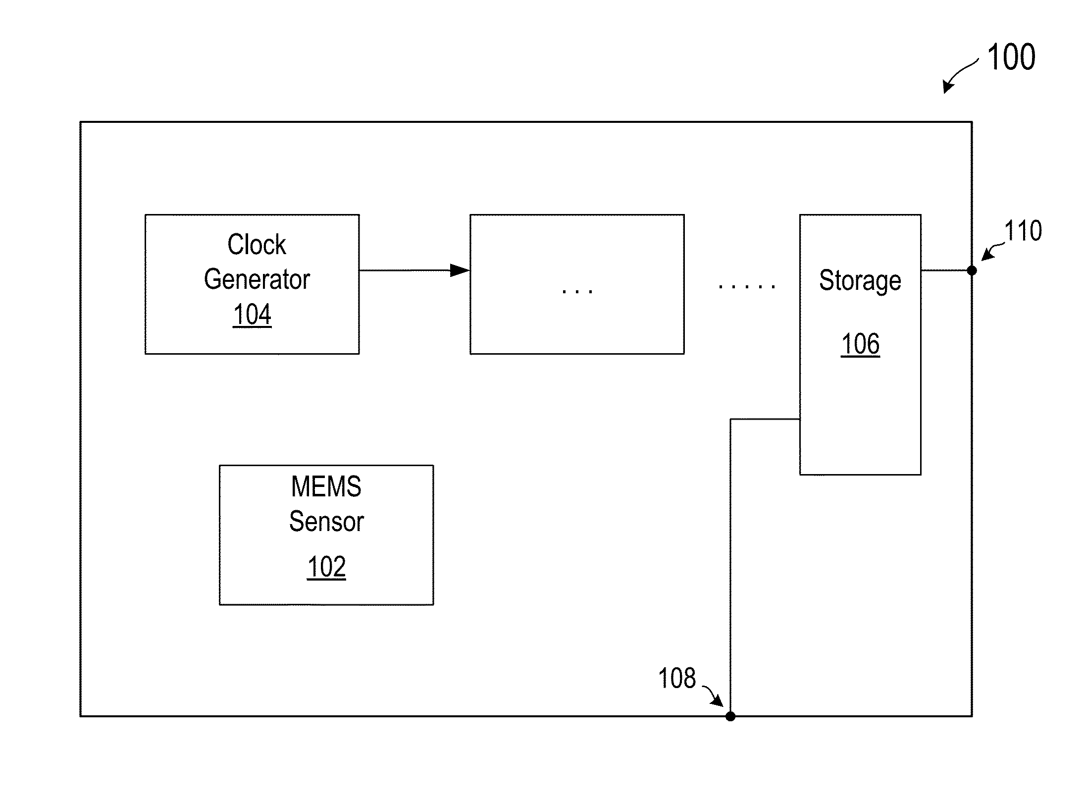
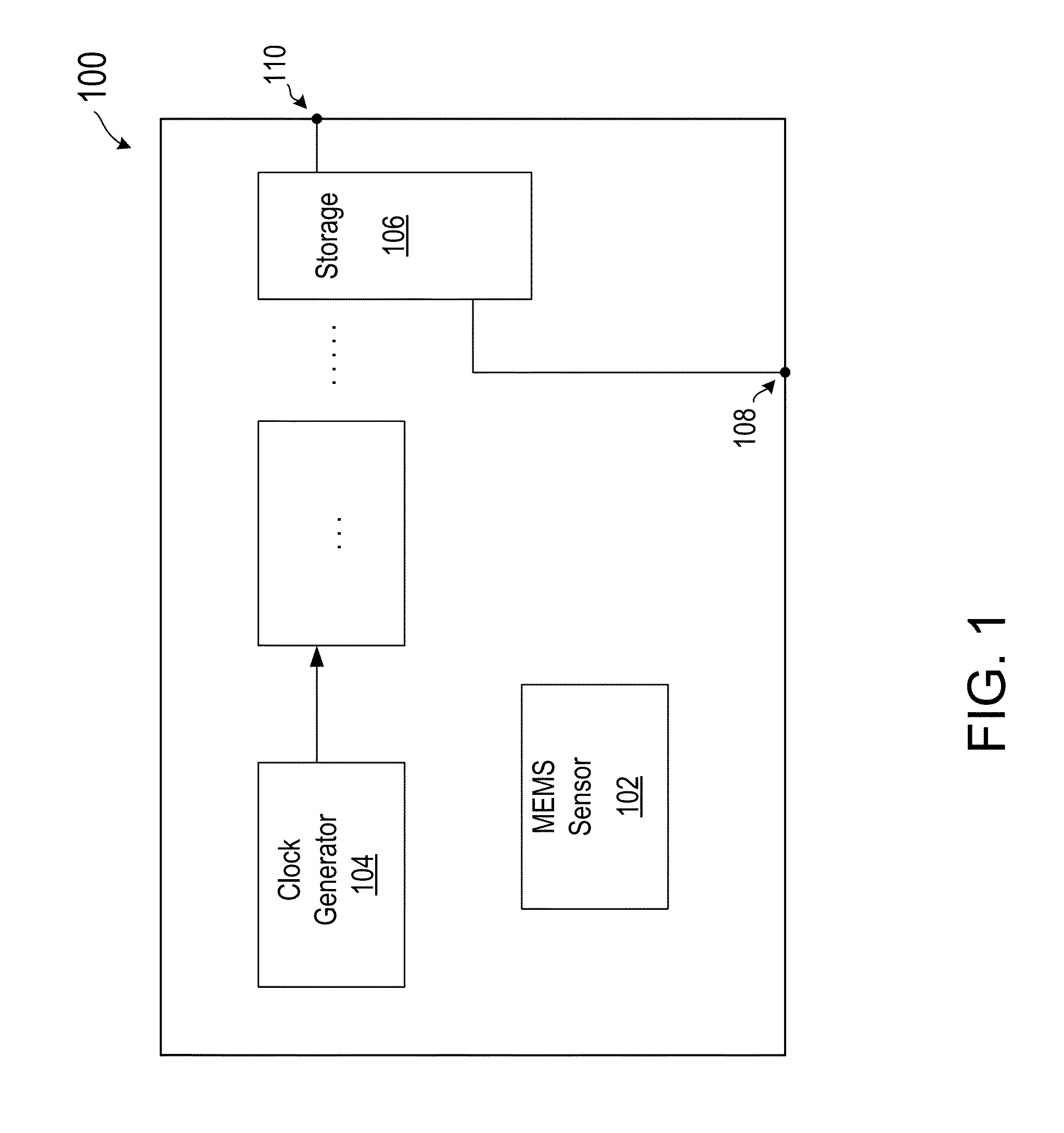
[0019]FIG. 1 illustrates a block diagram of a MEMS based device according to various embodiments of the present invention. As shown in FIG. 1, MEMS device 100 includes a MEMS sensor 102, an oscillator or clock generator 104 for providing a clock signal to the MEMS device, a storage unit 106, and other functional units. MEMS device 100 also includes an input terminal 108 for receiving a synchronization signal, and an output terminal 110 for providing access to the storage unit. MEMS device 100 is configured to receive, through the input terminal, the synchronization signal, and to store a local time in the storage unit upon receiving the synchronization signal. MEMS device 100 is also configured to perform a sensing operation to produce sensed data, and store, in the storage unit, the sense data ...


PUM


Abstract

A method is provided for time synchronization in a MEMS (MicroElectroMecahnical system) based system having a MEMS processor and a plurality of MEMS devices. In a specific embodiment, the method includes, in the MEMS processor, transmitting a synchronization signal to the plurality of MEMS devices and saving a local time upon transmitting the synchronization signal. The MEMS processor also receives sampled data and time information from the plurality of MEMS devices, when the data and information become available. The method also includes, in one or more of the MEMS devices, receiving the synchronization signal from the MEMS processor and storing a local time upon receiving the synchronization signal. The MEMS device also performs a sensing operation and stores sampled sense data and sense time information.

Description

CROSS-REFERENCES TO RELATED APPLICATIONS[0001]This application is a continuation application of U.S. patent application Ser. No. 13 / 758,929, filed Feb. 4, 2013, which claims priority to U.S. Provisional Patent Application No. 61 / 595,011, filed Feb. 3, 2012, commonly owned, the content of both of which is incorporated by reference herein for all purposes.BACKGROUND OF THE INVENTION[0002]The present invention relates to portable computing devices. More specifically, the present invention relates to a system and methods for timing synchronization in an MEMS (MicroElectroMechanical system) based system including a plurality of MEMS based device.[0003]Currently, more and more portable computing devices are becoming available to the average user / consumer. Such devices may include reader-type devices (e.g. Kindle, Nook), tablet-type devices (e.g. iPad, GalaxyTab), phone-type devices (e.g. iPhone, GalaxyS2), or the like. Many of these devices now include specialized hardware (e.g. MEMS devi...

Claims


Application Information

Patent Timeline
Patent Type & Authority Applications(United States)
IPC IPC(8): G06F1/14H04W52/02H04W56/00G06F1/12
CPCG06F1/14H04W56/001H04W52/029G06F1/12Y02D30/70
Inventor MILOTA, ANDYPRICE, JOBE
Owner DESIGN REACTOR
Why Eureka
Try Eureka