
Kneeling pad device

Inactive Publication Date: 2016-09-15
HATFIELD JOHN WINFRED
View PDF3 Cites 2 Cited by
  • Summary
  • Abstract
  • Description
  • Claims
  • Application Information

AI Technical Summary

Benefits of technology

The patent describes a kneeling pad that is attached to a retractable reel, which helps to protect the wearer's knees from injury during tasks. The device is portable, comfortable, and easy to use, so it can be carried without being noticed. The reel allows for the cord to be retracted and released, automatically adjusting its length. This feature helps to prevent the cord from being exposed and getting tangled, which could cause discomfort or injury. Overall, the invention provides a safer and more convenient way to protect the knees while performing various tasks.

Problems solved by technology

When kneeling regularly to carry out building work, gardening or other low-level manual tasks, knees can become painful or damaged.
The knee pad is difficult to slip due to the fixing clips.
Although knee pads have the advantage that they are worn and are therefore always available, they are often uncomfortable to wear for prolonged periods of time.
They ride up on clothing, promote clammy joints, can cause rashes, and are often ill-fitting.
This is not always practical when carrying other tools and because the requirement to kneel during a task is not always known in advance the kneeling pad is not always remembered or immediately to hand when required.
None of these other proposals provide a solution to the disadvantages of kneeling pads while being lightweight and retaining convenience, portability and enabling largely hands-free use.

Method used


Image

  • Kneeling pad device
  • Kneeling pad device
  • Kneeling pad device

Examples


Embodiment Construction

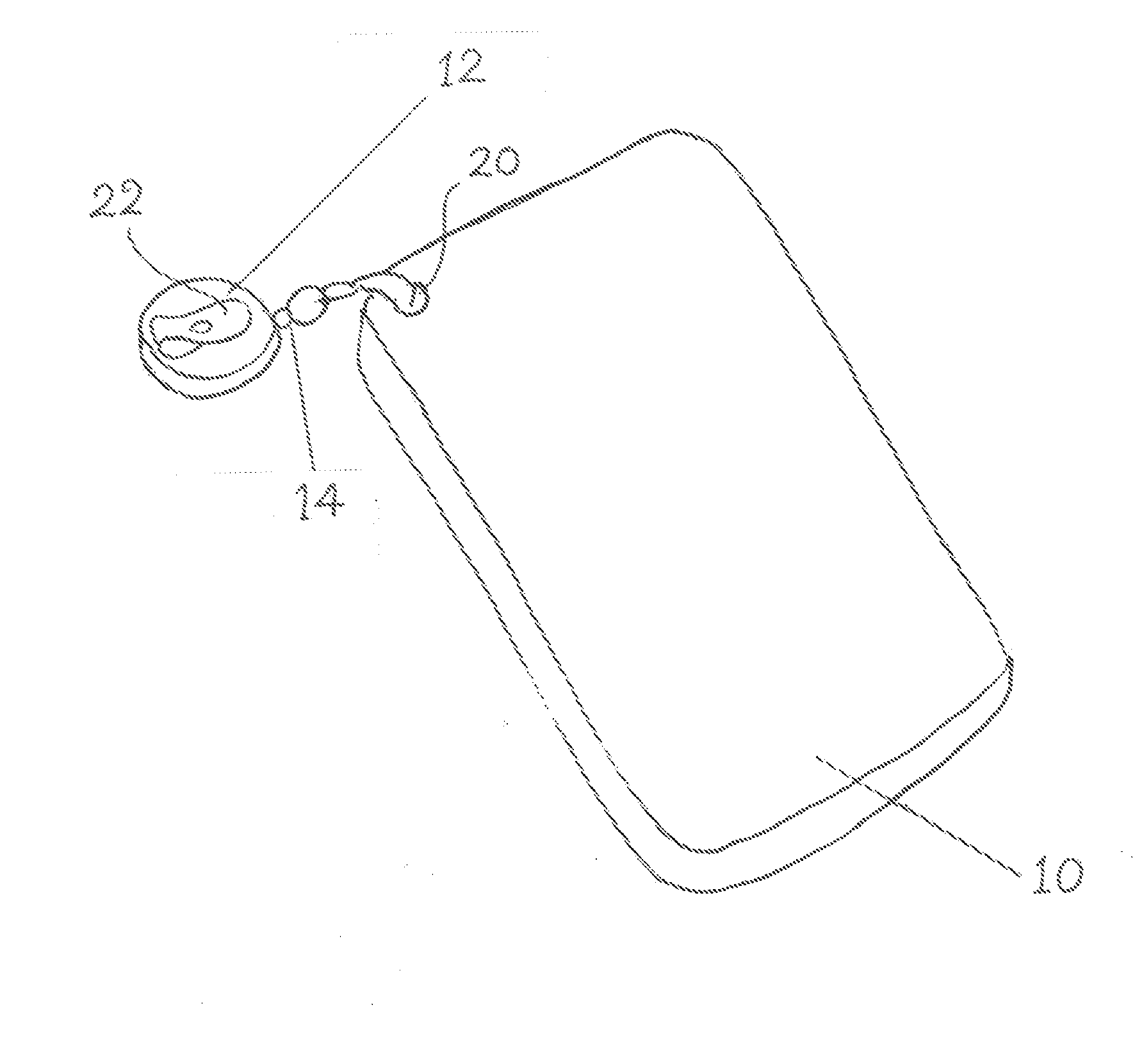
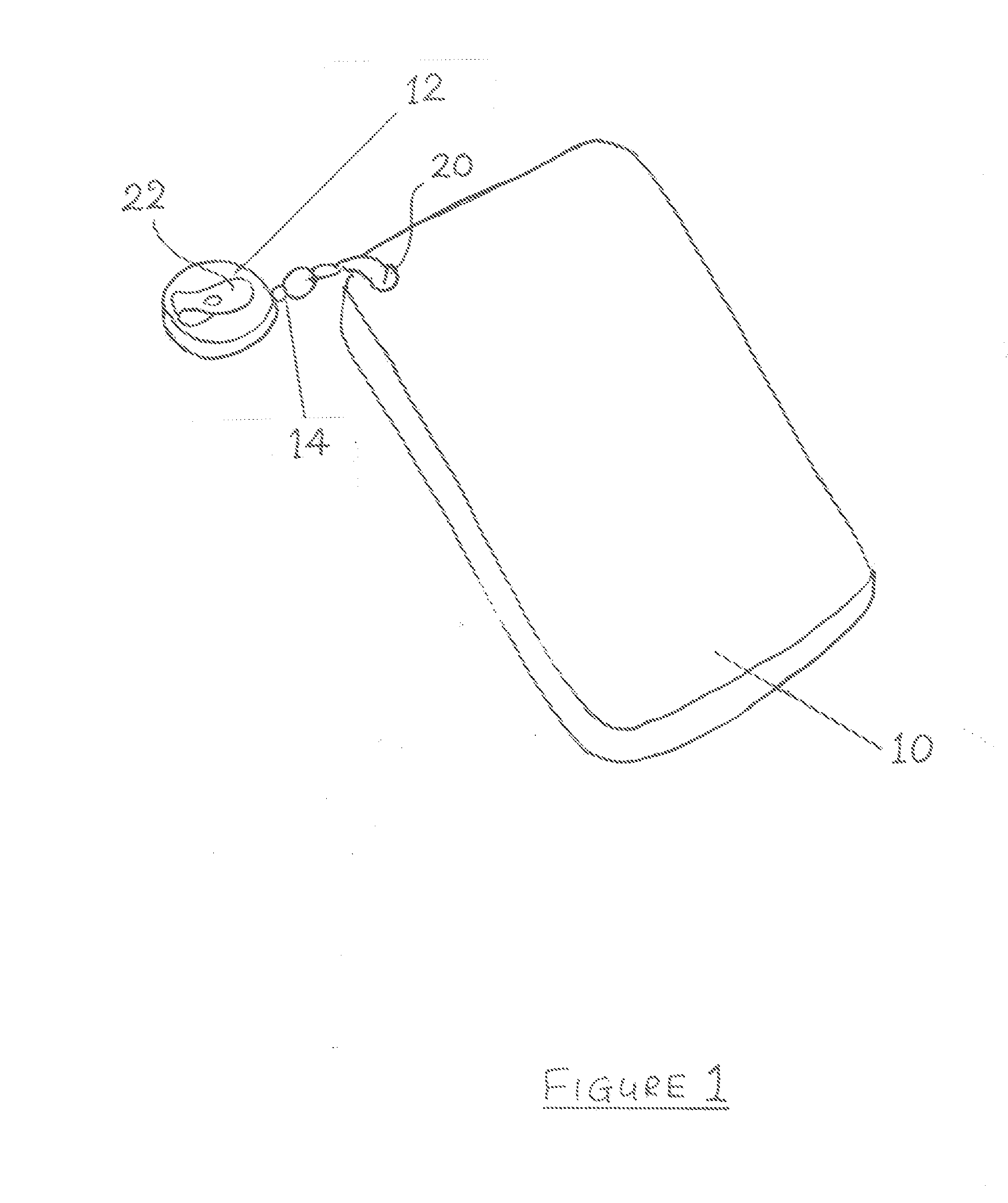
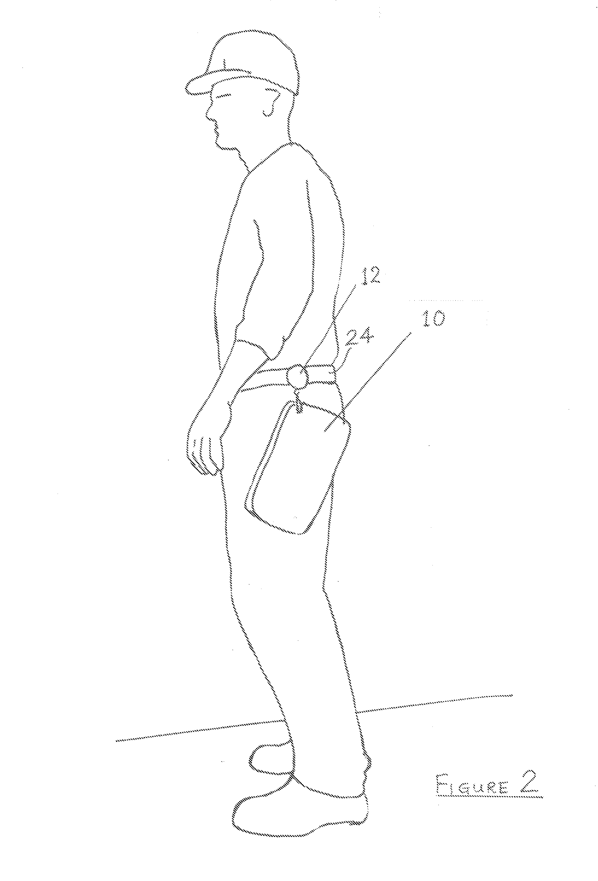
[0034]Referring to the drawings, a foam kneeling pad 10 having dimensions of 13 by 7 by 0.75 inches and formed of high density fire-resistant EVA foam material is attached to a retractable Teflon cord 14 housed in a reel 12 worn on a belt. The cord automatically retracts through a spring loaded mechanism of the reel. In this embodiment, the free end of the cord 14 is tied through a hole 20 adjacent one corner of the kneeling pad 10.

[0035]FIG. 1 shows the device not being worn, detailing the kneeling pad 10, the cord 14 in the fully retracted position and reel 12 incorporating a belt clip 22.

[0036]In the position shown in FIG. 2, the kneeling pad 10 is next to the reel 12 attached to a belt 24 on the user's left hip, and the cord is in the fully retracted position within the reel 12. In this position the kneeling pad is not obstructing the user from other tasks and it is within easy reach.

[0037]In the position shown in FIG. 3 the user is dropping to their knee whilst they place the k...


PUM


Abstract

The device has a kneeling pad (10) formed of an elastomeric material, the kneeling pad being connected to a cord (14). The cord has a remote end housed in a reel (12) into which the cord is capable of being retracted. The reel has can be attached to an item of clothing, such as the user's belt (24). The device ensures that when worn, knee protection is available to the wearer at all times negating the need for the user to remember to carry a kneeling pad between tasks. Easy availability also increases the likelihood of the kneeling pad being used for ad-hoc tasks therefore helping to reduce cumulative effects of minor stress on the knees.

Description

FIELD OF THE INVENTION[0001]This invention relates to a kneeling pad device and to a kit incorporating such a device.BACKGROUND[0002]When kneeling regularly to carry out building work, gardening or other low-level manual tasks, knees can become painful or damaged. Two common options for protecting the knees are (i) knee pads, and (ii) a kneeling pad.[0003](i) Knee pads, usually provided as a pair, attach to the user's knees, usually by means of straps passing behind the leg above and below the knee joint. Many examples of knee pads are known including the following:[0004]Chinese Utility Model CN 202311272-U (Univ Dezhou) relates to a knee pad characterized in that knee pad sheets, connected together by zips, are sealed on four sides to form a bag. Some of the knee pad sheets are provided with a hanging ring. Other knee pad sheets are provided with elastic bands, the upper ends of which are provided with fixing clips. The knee pad is difficult to slip due to the fixing clips.[0005]Ja...

Claims


Application Information

Patent Timeline
IPC IPC(8): A41D13/06
CPCA41D13/065A41D2600/20A41D2400/48A45F5/004A45F5/021A47C16/04
Inventor HATFIELD, JOHN WINFRED
Owner HATFIELD JOHN WINFRED
Learn More