Image reading apparatus
a reading apparatus and image technology, applied in the field of image reading apparatus, can solve the problems of uneven brightness of b>114/b> read images, and achieve the effect of reducing uneven illumination
- Summary
- Abstract
- Description
- Claims
- Application Information
AI Technical Summary
Benefits of technology
Problems solved by technology
Method used
Image
Examples
first embodiment
[0032]A first embodiment will be described below.
[0033](Image Reading Apparatus)
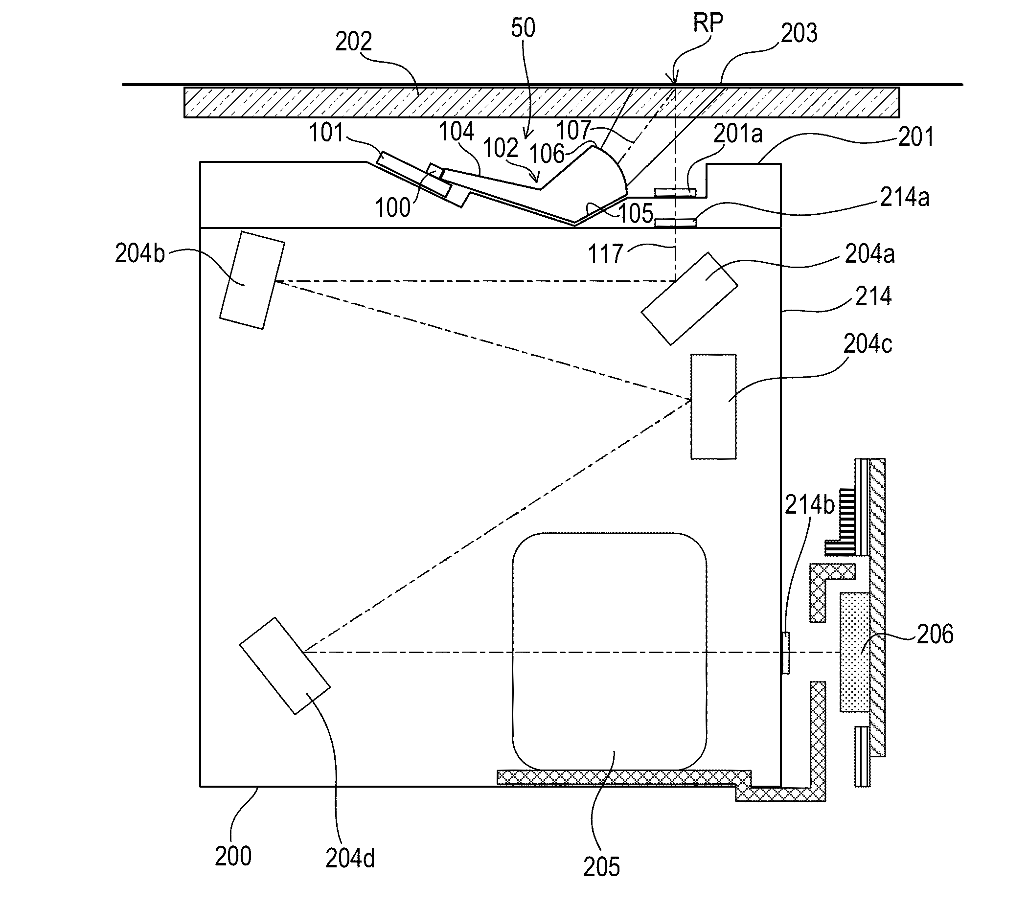
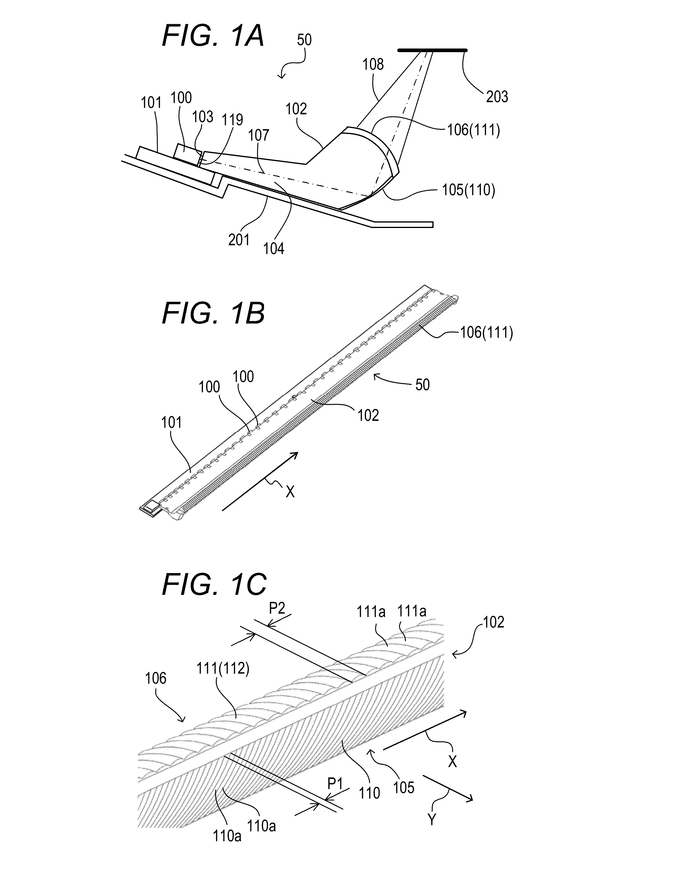
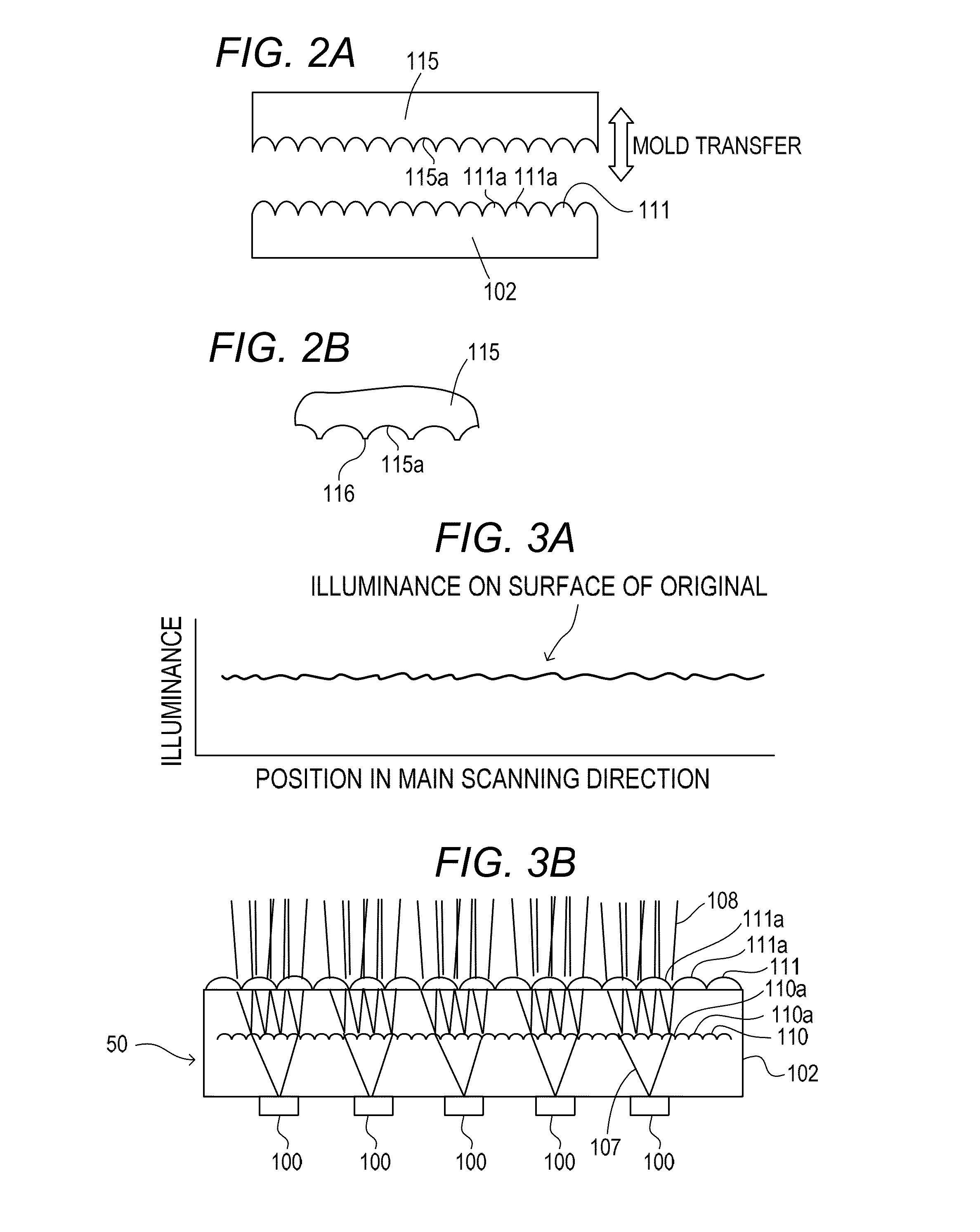
[0034]FIG. 5 is a cross-sectional view of an image reading apparatus 207 according to the first embodiment. The image reading apparatus 207 includes a main body 208, a platen glass 202 arranged on an upper portion of the main body 208, and an optical unit 200 movable in a sub-scanning direction Y inside the main body 208. The optical unit 200 is supported by a track 209 formed in the main body 208. The optical unit 200 is fixed to a belt 210 looped around a pair of pulleys 211 and 212. A motor 213 causes the pulley 211 to rotate forward and backward, to thereby rotate the belt 210 in directions indicated by the arrows C1 and C2. When the belt 210 is rotated forward by the motor 213 in the direction indicated by the arrow C1, the optical unit 200 moves along the track 209 in the sub-scanning direction Y. On the other hand, when the belt 210 is rotated backward by the motor 213 in the direction indicated b...
second embodiment
[0058]Next, a second embodiment will be described. In the second embodiment, the same components as those of the first embodiment are denoted by the same reference symbols and their description is omitted. An image reading apparatus, an optical unit, and an illumination device according to the second embodiment are the same as those according to the first embodiment and their description is omitted. A light guide according to the second embodiment will be described below.
[0059](Light Guide)
[0060]FIG. 6A and FIG. 6B are views for illustrating the illumination device 50 according to the second embodiment. FIG. 6A is a cross-sectional view for illustrating a sub-scanning cross-section of the illumination device 50. FIG. 6B is a partially enlarged view of the deflection surface 105 and the emission surface 106 of the light guide 102. A plurality of curved optical surfaces 120a and 121a are formed on the deflection surface 105 and the emission surface 106 side by side in the longitudinal...
third embodiment
[0068]Next, a third embodiment will be described. In the third embodiment, the same components as those of the first embodiment are denoted by the same reference symbols and their description is omitted. An image reading apparatus, an optical unit, and an illumination device according to the third embodiment are the same as those according to the first embodiment and their description is omitted. A light guide according to the third embodiment will be described below.
[0069](Light Guide)
[0070]FIG. 7A and FIG. 7B are views for illustrating the illumination device 50 according to the third embodiment. FIG. 7A is a cross-sectional view for illustrating a sub-scanning cross-section of the illumination device 50. FIG. 7B is a partially enlarged view of the deflection surface 105 and the emission surface 106 of the light guide 102. A plurality of curved optical surfaces 130a and 131a are formed on the deflection surface 105 and the emission surface 106 side by side in the longitudinal dire...
PUM
 Abstract
Description
Claims
Application Information
 - R&D
- Intellectual Property
- Life Sciences
- Materials
- Tech Scout
- Unparalleled Data Quality
- Higher Quality Content
- 60% Fewer Hallucinations
Browse by: Latest US Patents, China's latest patents, Technical Efficacy Thesaurus, Application Domain, Technology Topic, Popular Technical Reports.
© 2025 PatSnap. All rights reserved.Legal|Privacy policy|Modern Slavery Act Transparency Statement|Sitemap|About US| Contact US: help@patsnap.com


