Image-displaying apparatus

a technology of image displaying and auxiliary equipment, which is applied in the direction of fixed installation, lighting and heating equipment, instruments, etc., can solve the problems of low conversion efficiency from input power to light, shortened life span, and inability to couple the cable stitch lens unit to the leds, so as to reduce the uneven illumination of the light valve

Inactive Publication Date: 2006-03-02
RICOH KK
View PDF9 Cites 32 Cited by
  • Summary
  • Abstract
  • Description
  • Claims
  • Application Information

AI Technical Summary

Benefits of technology

[0018] The present invention, which has been made in view of the above problems, is to provide an image-displaying apparatus which can reduce uneven illuminance of a light valve and can perform bright illumination even if the F-number is large. The invention is to further provide a projector and an image observing apparatus each using such an image-displaying apparatus.
[0040] When the secondary light source-forming prism is coupled with each of the light-emitting diodes and the light flux emitted from each of the light-emitting diodes is divided into plural ones (at least five), the effect of the oriented light distribution and characteristics of the light-emitting diode upon the uneven illuminance can be reduced.
[0041] Further, when the secondary light source-forming prism is used as in the present invention, the using efficiency of the light can be enhanced as compared with the conventional technique. Thus, the image-displaying apparatus having high light takeout efficiency from the light-emitting diode, that is, the bright image-displaying apparatus can be realized.

Problems solved by technology

Since the above thermal light source is used as an illuminating light source, an input electric power needs to be large, because the conversion efficiency from the input power to the light is low.
Consequently, dimensions of the power source and the lamp (which is provided with a reflector mirror in many cases) become large, and a cooling fan is necessary, Thus, such a system is heavy, and the span of life is shortened because of heat in the case of the light valve, particularly the liquid crystal valve.
However, it is not practical to couple the cable stitch lens unit to the LEDs.
Even if the former is coupled to the latter, the size of each of lenses constituting the cable stitch lens unit becomes extremely small.
If the light is led from each of the LEDs to the light valve as much as possible, the F-number of the release lens system for leading the light from the LEDs to the light valve becomes smaller, which results in the increased lens diameter and the increased number of the aberration-correcting lenses.

Method used


Image

  • Image-displaying apparatus
  • Image-displaying apparatus
  • Image-displaying apparatus

Examples


first embodiment

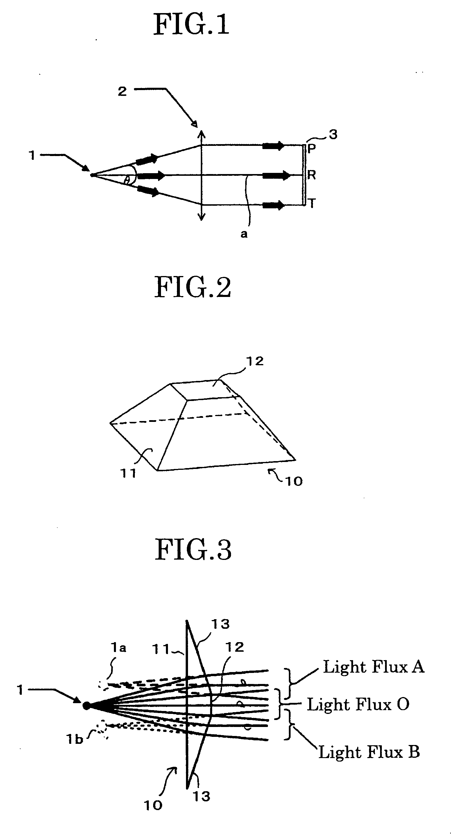
[0065]FIG. 2 shows the structure of a secondary light source-forming prism in the image-displaying apparatus according to the present invention. The secondary light source-forming prism 10 comprises two rectangular planes: a first rectangular plane 11 and a second rectangular plane 12 and four trapezoidal planes. Since the aspect ratio of the light valve 3 in FIG. 1 is set at 1:1, explanation will be made in the present embodiment on the assumption that the rectangular planes of the secondary light source-forming prism 10 are square. The shape of the retangular planes can be arbitrarily selected depending upon the aspect ratio of the lens bulb 3.

[0066]FIG. 3 shows the construction of the LED portion using the above secondary light source-forming prism.

[0067] The LED section shown in FIG. 3 is constituted by the LED 1 of FIG. 1 as the point-source light and the secondary light source-forming prism 10 of FIG. 2 which is arranged near the LED 1. In this case, as shown in FIG. 3, the l...

second embodiment

[0081] Next, the image-displaying apparatus according to the present invention will be explained below.

[0082] The image-displaying apparatus according to the second embodiment shows the illuminance distribution when the solid angle θ of the emitted light flux of the LED in the same orientated light distribution as in the first embodiment is further taken in a range of 30 degrees to 60 degrees.

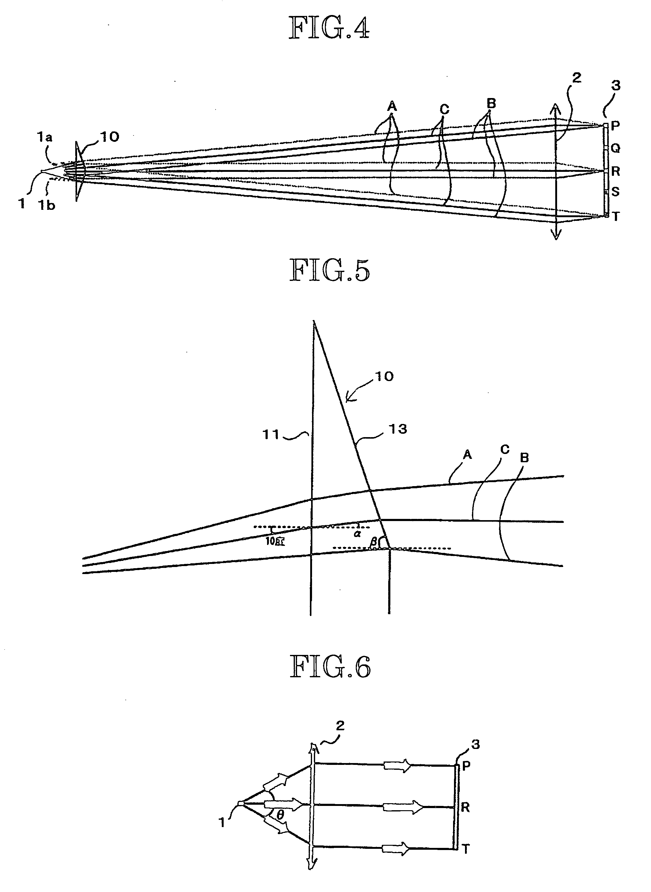
[0083]FIG. 6 shows the construction of an image-displaying apparatus in which no secondary light source-forming prism is disposed. FIG. 7 shows the construction of an image-displaying apparatus in which a secondary light source-forming prism is disposed. In this case, the open angle of the trapezoid of the secondary light source-forming prism 20 from the LED along the optical axis is larger as compared with the first embodiment. Corresponding to this, when the light fluxes are traced, an end portion of each of the light fluxes A and B does not enter the light valve 3, resulting in a loss, whic...

third embodiment

[0089] Next, the image-displaying apparatus according to the present invention will be explained.

[0090]FIG. 8 shows the construction of an LED portion utilizing a secondary light source-forming prism as the third embodiment.

[0091] The secondary light source-forming prism shown in FIG. 8 has a second rectangular plane 31 having a curved face on a light-emitting side. In this case, as shown in FIG. 8, the virtual image of the light source of the central light flux is aligned with locations 1a, 1b of the secondary light sources in the optical-axis direction of the light fluxes passing trapezoidal planes 32 of the secondary light source-forming prism 30. This LED portion is more preferable than that explained in the first embodiment.

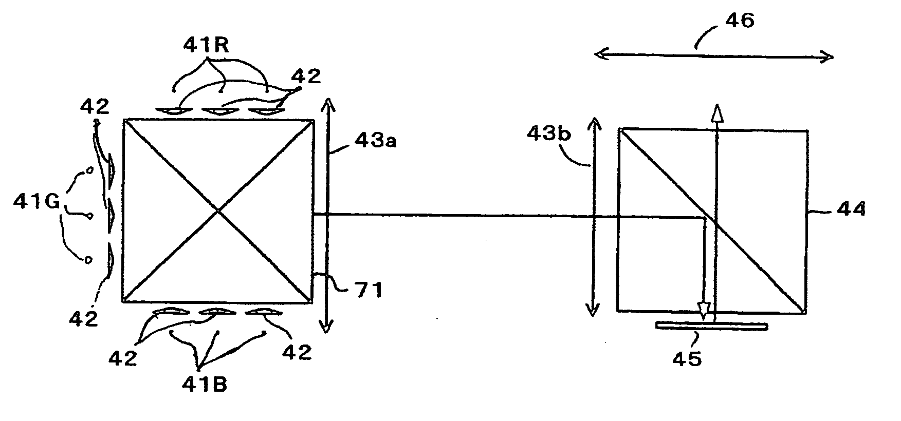
[0092]FIG. 9 shows the construction of a color image-displaying apparatus to which the image-displaying apparatus of the present invention is applied.

[0093] A color image-displaying apparatus shown in FIG. 9 comprises a red LED 41R, a green LED 41G, a blu...


PUM


Abstract

An image-displaying apparatus comprising a light-emitting diode, a relay lens, a secondary light source-forming prism arranged between the light-emitting lens and the relay lens, and a light valve, said secondary light source-forming prism having opposed first and second opposed rectangular planes and at least four polygonal planes, said first and second rectangular planes being positioned on sides of the light-emitting diode and the light valve, respectively, and an area of the first rectangular plane being greater than that of the second rectangular plane, wherein a light emitted from the light-emitting diode is illuminated upon the light valve through the relay lens and the secondary light source-forming prism.

Description

[0001] This application claims the convention priority of Japanese Patent Application No. 2004-253052 filed on Aug. 31, 2004, the disclosure of which is entirely incorporated herein by reference. BACKGROUND OF THE INVENTION [0002] 1. Field of the Invention [0003] The present invention relates to an image-displaying apparatus, particularly suitable for a projector or an image-observing apparatus. [0004] 2. Related Art Statement [0005] There are currently, commonly available two types of color display methods for projectors. One type is a color-mixing method in which light emitted from a white thermal light source is divided into three primary colors: red, green and blue, three light valves are illuminated with three color lights, respectively, the lights modulated by the respective light valves are combined with a color-combining optical system such as a cross dichroic prism, and an illumination light of the three primary colors modulated by the light valves is constantly illuminated...

Claims


Application Information

Patent Timeline
Patent Type & Authority Applications(United States)
IPC IPC(8): F21V9/00H01L33/58
CPCH04N9/3114H04N9/3197H04N9/315
Inventor TATSUNO, HIBIKI
Owner RICOH KK
Why Eureka
Try Eureka