Illumination device

Active Publication Date: 2018-05-24
DAI NIPPON PRINTING CO LTD
View PDF2 Cites 7 Cited by
  • Summary
  • Abstract
  • Description
  • Claims
  • Application Information

AI Technical Summary

Benefits of technology

[0059]According to the second embodiment of the present invention, the illumination device can sufficiently utilize per

Problems solved by technology

Thus, it is impossible to sufficiently utilize performance of the light source so

Method used


Image

  • Illumination device
  • Illumination device
  • Illumination device

Examples


first embodiment

[0075]A first embodiment is firstly described with reference to an example shown in FIGS. 1 to 6.

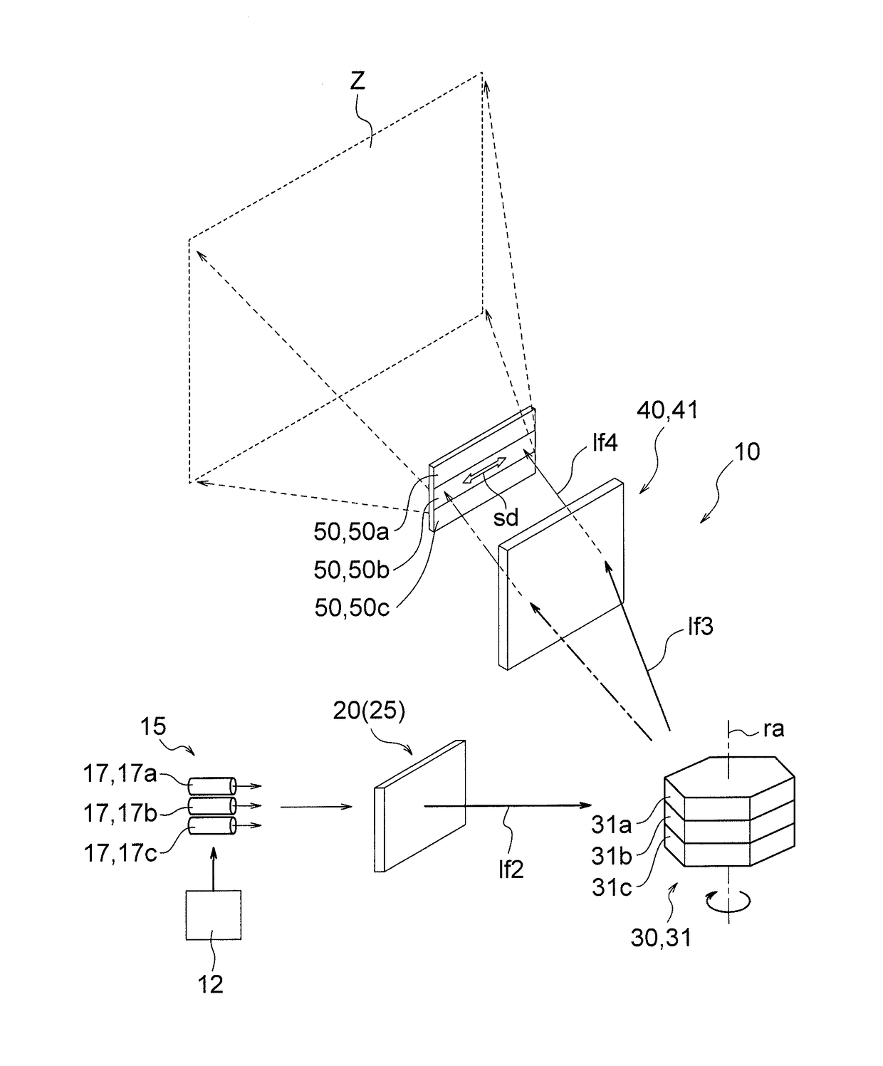
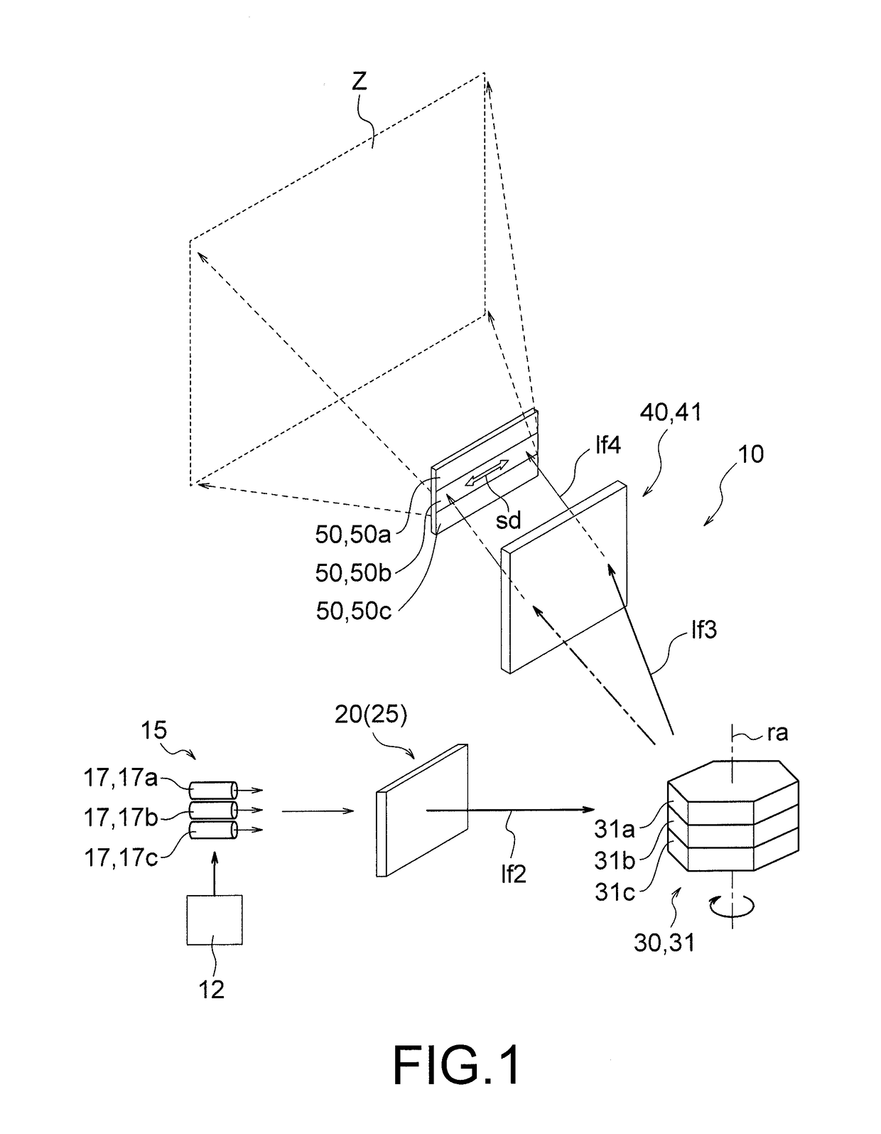
[0076]FIG. 1 is a perspective view schematically showing an overall structure of an illumination device 10. The illumination device 10 illuminates an illumination area Z by using coherent light. The illumination device 10 includes a laser light source 15 functioning as a coherent light source. The laser light source 15 oscillates laser light (laser beam) which is an example of coherent light. The illumination device 10 includes a shaping optical system 20, a scanner 30, a light condensing optical system 40 and a light diffusion device 50, which process light emitted from the laser light source 15. In the example shown in FIG. 1, the shaping optical system 20, the scanner 30, the light condensing optical system 40 and the light diffusion device 50 are located in this order along a light path of laser light from the laser light source 15, and they process laser light in this order. As desc...

second embodiment

[0140]Next, a second embodiment is described with reference to an example shown in FIGS. 7 to 13.

[0141]FIG. 7 is a perspective view schematically showing an overall structure of an illumination device 110. The illumination device 110 illuminates an illumination area Z using coherent light such as laser light (laser beam). The illumination device 110 includes, as a light source, a laser light source 115 that oscillates laser light. The laser light source 115 oscillates laser light that is coherent light. The illumination device 110 includes a diffusion optical system 120, a scanner 130, a light condensing optical system 140 and a light deflection device 150, which process light emitted from the laser light source 115. In the example shown in FIG. 7, the diffusion optical system 120, the scanner 130, the light condensing optical system 140 and the light deflection device 150 are located in this order along a light path of laser light from the laser light source 115, and they process l...


PUM


Abstract

An illumination device (10) includes: a light diffusion device (50) including element diffusion devices (55) that diffuse incident light; a coherent light source (15) that emits coherent light; a shaping optical system (20) that shapes the coherent light; a scanner (30) that adjusts a traveling direction of the coherent light so as to allow the coherent light to scan the light diffusion device; and a light condensing optical system located on a light path of the coherent light from the shaping optical system up to the light diffusion device. The light condensing optical system condenses the coherent light such that a spot area on the light diffusion device is smaller than the element diffusion device. Each element diffusion device diffuses the coherent light incident thereon so as to illuminate an element illumination area corresponding to the element diffusion device.

Description

TECHNICAL FIELD[0001]The present invention relates to an illumination device that illuminates a predetermined area by using light.BACKGROUND ART[0002]As disclosed in JP2012-146621A, for example, an illumination device using a coherent light source is widely used. A laser light source that oscillates laser light (laser beam) is typically used as the coherent light source.[0003]JP2012-146621A discloses a vehicle lighting tool. The vehicle lighting tool includes a light source, which can be formed by a laser oscillation device, and four hologram devices. The respective hologram devices are moved by a rotating and driving apparatus to be located on positions where they can receive laser light from the light source. The respective hologram devices diffract the laser light to achieve illumination in a desired light distribution pattern. By suitably selecting a hologram device which is irradiated with laser light, illumination in a predetermined light distribution pattern can be achieved. ...

Claims


Application Information

Patent Timeline
IPC IPC(8): F21K9/233F21K9/60G02B27/48
CPCF21K9/233F21K9/60G02B27/48G02B26/12F21S41/16F21S41/176F21V5/04F21V5/02G03H2001/2223G03H1/2286G03H2001/2292G03H2001/2218
Inventor KURASHIGE, MAKIO
Owner DAI NIPPON PRINTING CO LTD
Why Eureka
Try Eureka