Illuminating temperature indicator

Inactive Publication Date: 2007-02-01
CURRIE JOSEPH EDWARD
View PDF12 Cites 6 Cited by
  • Summary
  • Abstract
  • Description
  • Claims
  • Application Information

AI Technical Summary

Benefits of technology

[0022] A further objective of the present invention is to provide an improved fluid illumination device that, in an alternative embodiment, may be made completely portable and that is disposed completely outside of any fluid conduit, pi

Problems solved by technology

Heated oil pipe lines inspected from the air by helicopter or stol type pipeline patrol aircraft presently are inspected for leaks or structural damage, but there does not presently exist a way for patrol aircraft to determine if the oil temperature within the pipeline is correct, and if not correct at what location along the pipeline the temperature decreases.
Scalding hot liquid from a tap or other liquid outlet often warns the user by emanating visible vapor, however liquids of 160 degrees Fahrenheit or hotter do not always warn of hot temperature with vapor.
While there may be some vapor emanating from some hot fluids, this is not always the case, and it can be difficult to determine the temperature of a flowing liquid without touching the liquid flow.
Moreover, it often takes some time, (perhaps a minute or s

Method used


Image

  • Illuminating temperature indicator
  • Illuminating temperature indicator
  • Illuminating temperature indicator

Examples


Example

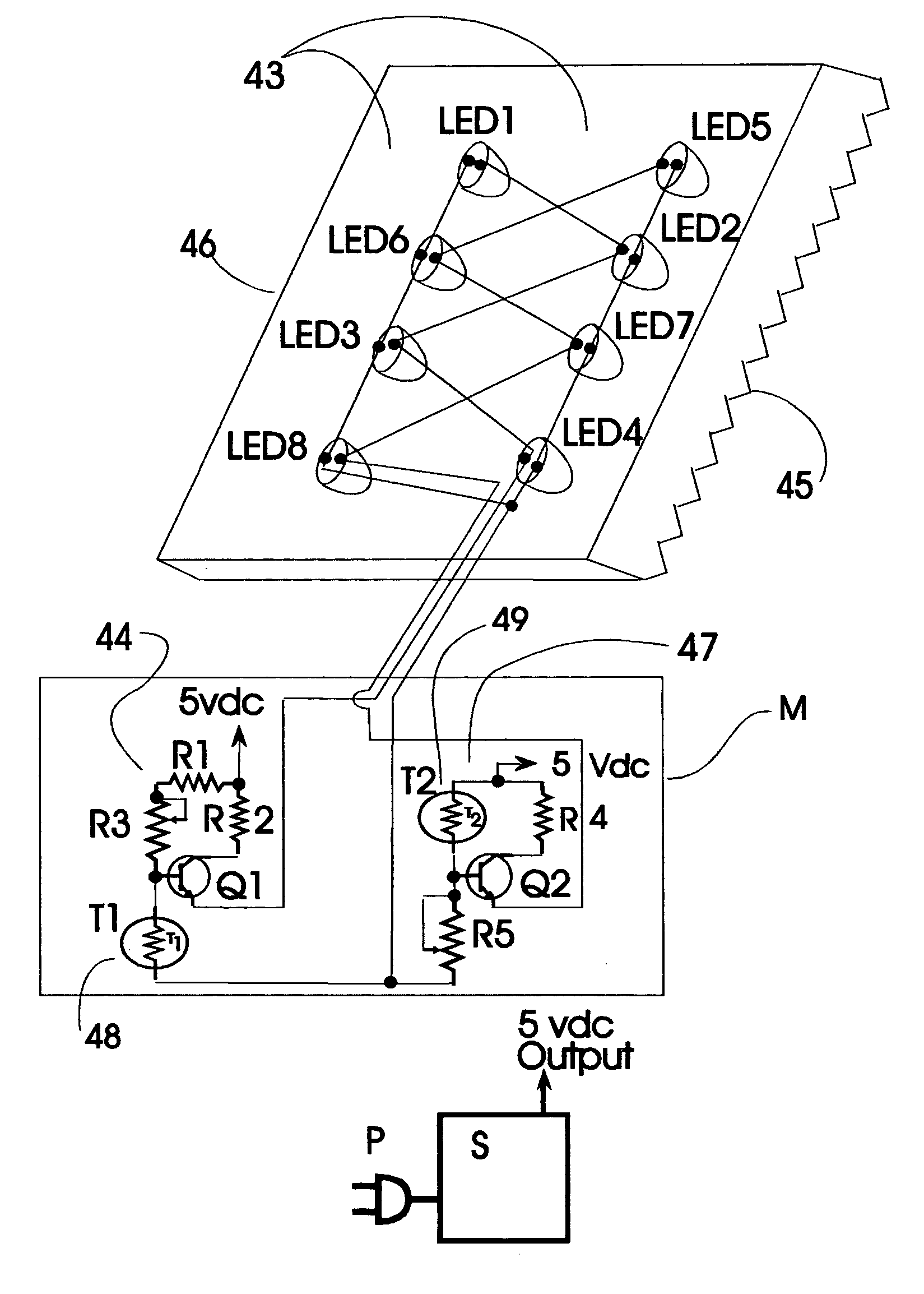
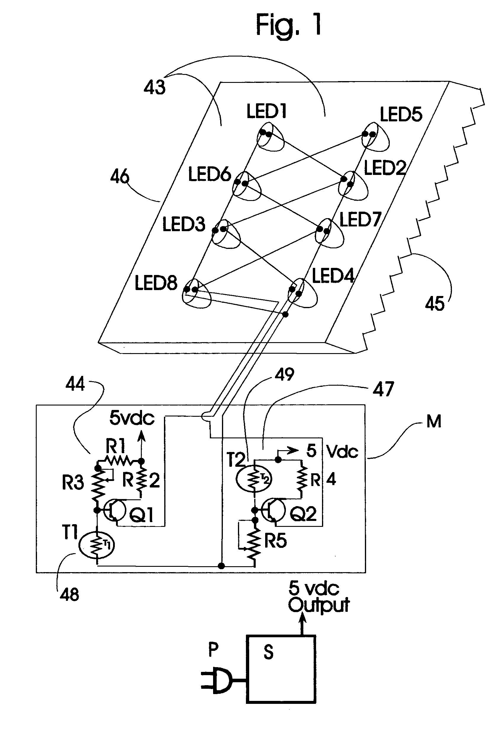
[0030] Referring now particularly to FIG. 1 of the drawings, the present invention will be seen to relate to a device providing for the automatic illumination of acrylic indicator 46, with triangular grooves 45, and light reflective surface 43, that displays a color indicating the temperature of a fluid that is within a conduit or container, and the apparatus comprising the device. Two electronic control circuits 44 and 47 of the present invention are mounted in control box M, or in the base of indicator 46, or in associated power supply unit S. Control circuit 44 modulates the voltage to red LEDs 1 through 4, and control circuit 47 modulates the voltage to blue LEDs 5 through 8, so that the illumination mixing and blending qualities of acrylic indicator 46 provide a continuous change of color of acrylic indicator 46 as the temperature of a monitored liquid changes.

[0031] The color of acrylic indicator 46 will vary from blue, through shades of magenta, to red, as the temperature of...


PUM


Abstract

An illuminating acrylic temperature-indicating device that provides for a visual temperature indication of a fluid within a conduit, or a storage tank. The acrylic indicator mixes and blends the illumination from imbedded blue LEDs and red LEDs and separate electronic control circuits control each color of LEDs with separate temperature sensing thermistors. The indicator glows with blue, shades of magenta, and red colors as the temperature of a monitored liquid changes from cold to hot. The individual control circuits that control the illumination modulation intensity of the red and blue LEDs each provide a user with a manual adjustment that allows a user to set the hot and cold temperature sensing parameters of the device. The acrylic indicator illuminates with enough light intensity to be visible under all normal lighting conditions and is intended to operate continuously.

Description

CROSS REFERENCE TO RELATED APPLICATIONS [0001] Please refer to Provisional application No. 60 / 702,238, filing date Jul. 26, 2005.STATEMENT REGARDING FEDERALLY SPONSORED RESEARCH OR DEVELOPMENT [0002] (Not Applicable) BACKGROUND OF THE INVENTION [0003] Heated oil pipe lines inspected from the air by helicopter or stol type pipeline patrol aircraft presently are inspected for leaks or structural damage, but there does not presently exist a way for patrol aircraft to determine if the oil temperature within the pipeline is correct, and if not correct at what location along the pipeline the temperature decreases. One embodiment of the present invention places illuminating liquid temperature indicators on above ground pipelines that are visible from the air or ground. [0004] In another embodiment of the present invention a user of a tap or other fluid outlet is warned of hot liquid. Scalding hot liquid from a tap or other liquid outlet often warns the user by emanating visible vapor, howe...

Claims


Application Information

Patent Timeline
IPC IPC(8): G08B17/00
CPCG01K1/143G01K1/02
Inventor CURRIE, JOSEPH EDWARD
Owner CURRIE JOSEPH EDWARD
Why Eureka
Try Eureka