Vehicular cornering lamp

a technology of cornering lamps and lamps, which is applied in the field of vehicle lamps, can solve problems such as problems, and achieve the effects of increasing the light intensity area, and increasing the visibility of the road surface in front of the vehicl

Inactive Publication Date: 2006-02-07
KOITO MFG CO LTD
View PDF9 Cites 7 Cited by
  • Summary
  • Abstract
  • Description
  • Claims
  • Application Information

AI Technical Summary

Benefits of technology

[0019]A vehicular lamp according to the present invention has a configuration in which the light source bulb includes a front filament and a rear filament positioned substantially in series along a central axis of the bulb and a bulb shade provided below and adjacent the front filament for blocking light from the front filament radiated in the direction of a lower reflecting area of the reflecting surface so as to allow light from the front filament to strike only the upper reflecting area of the reflecting surface, and a second shade is provided above and adjacent of the light source bulb for blocking light from the rear filament radiated toward the upper reflecting area so as to allow light from the rear filament to strike only the upper reflecting area. Therefore, the usable area of the reflecting surface of a reflector can be changed by switching the lighting between the front filament and the rear filament. That is, when the front filament is illuminated beam can be irradiated by using the upper reflecting area, while when the rear filament is illuminated beam can be irradiated by using the lower reflecting area.
[0020]In addition, the vehicular lamp is configured such that a first light distribution pattern which is formed on the road surface in front of a vehicle by light reflected from the upper reflecting area when the front filament is illuminated, is formed farther from the vehicle than a second light distribution pattern which is formed on the road surface in front of the vehicle by light reflected from the lower reflecting area when the rear filament is illuminated. As a result, the first light distribution pattern has a clear cut-off line caused by the bulb shade disposed adjacent to the front filament, and a high light intensity area is formed along the cut-off line. Therefore, long distance visibility of the road surface in front of the vehicle is increased by forming the first light distribution pattern farther from the vehicle than the second light distribution pattern.
[0021]In this manner, in a vehicular cornering lamp according to the present invention which radiates beams toward the road surface in front of the vehicle in predetermined light distribution patterns, beams can be radiated in different light distribution patterns in accordance with vehicle driving conditions. As a result, the visibility of the road surface in front of the vehicle can be increased. Moreover, this effect can be achieved with a very simple configuration of filament switching using a single light source bulb.
[0022]If the light source bulb is supported by the reflector with the central axis thereof tilted upward with respect to the optical axis of the reflector at a predetermined angle, the usable luminous flux of the front filament can be increased. In addition, if a light source bulb such as a halogen bulb of the H4 type having a bulb shade that surrounds the front filament at a center angle of less than 180° is employed, it is easily possible to form the first light distribution pattern with a horizontal cut-off line on the upper end edge. Also, a high light intensity area can be formed below and in the vicinity of the horizontal cut-off line.
[0024]Further, if the rear filament is illuminated when the vehicle speed is equal to or less than a predetermined vehicle speed, and if the front filament is illuminated when the vehicle speed is greater than the predetermined vehicle speed, while driving at low speeds when the eyes of the driver are on the short distance road surface, the short distance road surface will be broadly and substantially uniformly illuminated and most of the long distance road surface is not illuminated. On the other hand, while driving at medium and high speeds when the eyes of the driver are on the long distance road surface, the long distance road surface will be illuminated brightly and most of the short distance road surface is not illuminated. Thus, visibility can be further increased by illuminating the road surface in front of the vehicle with light distribution patterns appropriate to current speed.
[0026]Further, if the second light distribution pattern is made to extend further in the widthwise direction of the vehicle than the first light distribution pattern, while driving at low speeds when the eyes of the driver are on the short distance road surface, the visibility of the short distance road surface in front of the vehicle in the turning direction can be sufficiently ensured, while when driving at medium and high speeds when the eyes of the driver are on the long distance road surface, the visibility of the long distance road surface in front of the vehicle in the turning direction is also sufficient.

Problems solved by technology

However, the conventional cornering lamp, which is configured so as to radiate a beam in a single light distribution pattern Pa′, has the following problems.
These problems can also occur in the case of a vehicular lamp other than a cornering lamp.

Method used


Image

  • Vehicular cornering lamp
  • Vehicular cornering lamp
  • Vehicular cornering lamp

Examples


Embodiment Construction

[0037]A preferred embodiment of a vehicular lamp constructed according to the present invention will be explained with reference to the accompanying drawings.

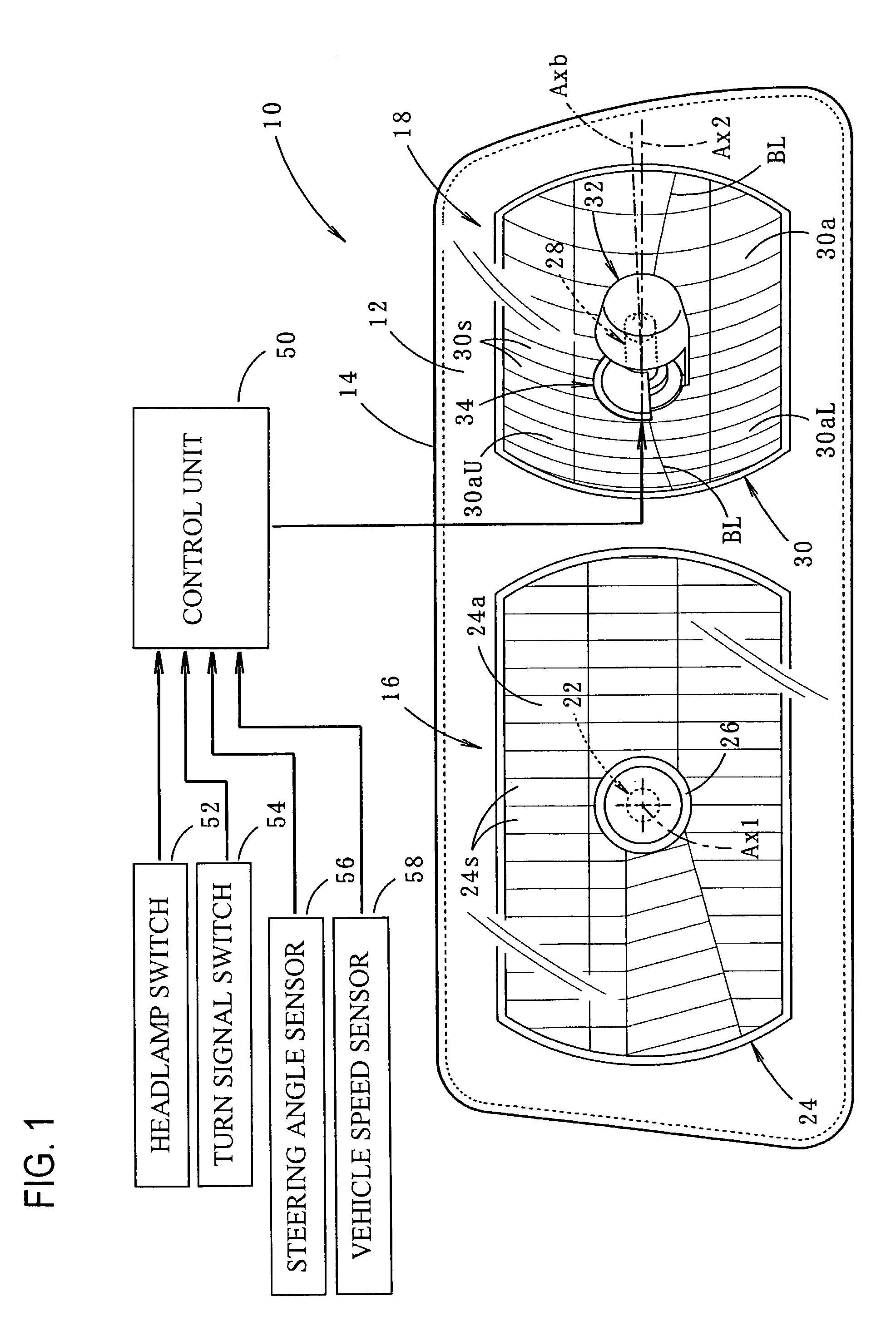
[0038]FIG. 1 is a front view of a preferred embodiment of a vehicular lamp 10 of the present invention along with a control system for the lamp.

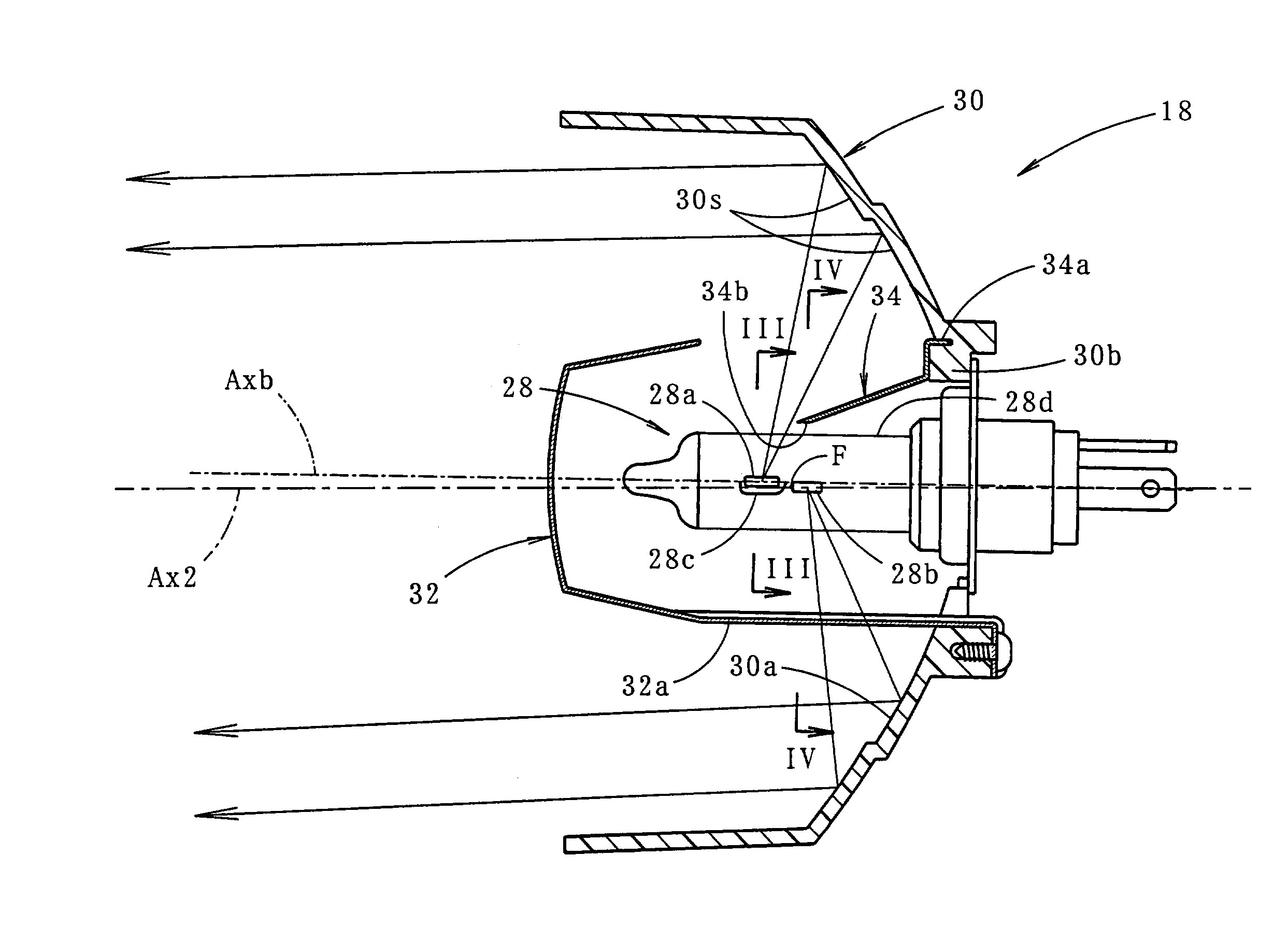
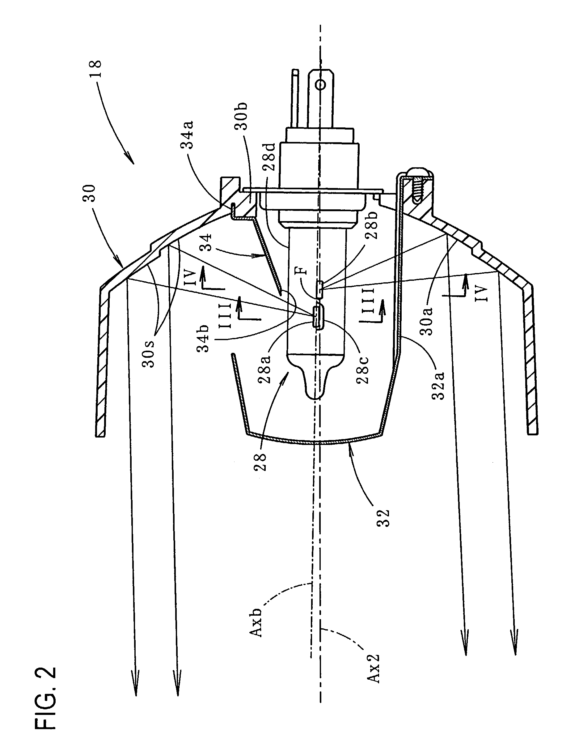
[0039]As shown in the FIG. 1, the vehicular lamp 10, which is designed to be mounted on the left side of the front portion of a vehicle, functions both as an ordinary headlamp and as a cornering lamp which provides a beam in front of the vehicle in the turning direction when the vehicle is executing a turn.

[0040]More specifically, in the vehicular lamp 10 a headlamp unit 16 and a cornering lamp unit 18 are accommodated in a lamp chamber formed by a plain translucent cover 12 and a lamp body 14. As will be described in more detail below, beam radiation from the cornering lamp 18 is controlled by a control unit 50 in accordance with current driving conditions.

[0041]The headlamp unit 16, w...


PUM


Abstract

A vehicular cornering lamp which radiates beams having different light distribution patterns in accordance with different driving conditions such as different driving speed ranges. A bulb shade blocks light from a front filament from reaching a lower reflecting area on a reflecting surface of the reflector of the lamp while allowing light from the front filament to strike only an upper reflecting area, while an upward light blocking shade provided above and adjacent the light source bulb blocks light from the rear filament from reaching the upper reflecting area while allowing light from the rear filament to strike only the lower reflecting area. The active area of the reflecting surface of the reflector can be changed by switching illumination between the front filament and the rear filament.

Description

CROSS-REFERENCE TO RELATED APPLICATIONS[0001]Not applicableSTATEMENT REGARDING FEDERALLY SPONSORED RESEARCH OR DEVELOPMENT[0002]Not applicableREFERENCE TO SEQUENCE LISTING, A TABLE, OR A COMPUTER PROGRAM LISTING COMPACT DISK APPENDIX[0003]Not applicableBACKGROUND OF THE INVENTION[0004]The present invention relates to a vehicular lamp which is configured so as to provide a beam of light on a road surface in front of the vehicle with a predetermined light distribution pattern while the vehicle is turning or executing a corner.[0005]Conventionally, a cornering lamp, which is a vehicular lamp other than a headlamp, has been known which provides a beam on the road surface in front of the vehicle when the vehicle is turning, thus increasing the visibility of the road surface in the turning direction.[0006]FIGS. 11A and 10B show light distribution patterns Pa′ formed on the road surface in front of a vehicle by a beam from a conventional cornering lamp produced when the vehicle is making a...

Claims


Application Information

Patent Timeline
Patent Type & Authority Patents(United States)
IPC IPC(8): F21V11/00B60Q1/12B60Q1/14B60Q1/18F21S8/10F21V14/02F21W101/10F21Y101/00
CPCB60Q1/12B60Q1/18B60Q2300/054F21S48/1145B60Q2300/122B60Q2300/142B60Q2300/112F21S41/14
Inventor KINOUCHI, TOSHIYUKI
Owner KOITO MFG CO LTD
Why Eureka
Try Eureka