Image reading apparatus

a reading apparatus and image technology, applied in the field of image reading apparatus, can solve the problems of uneven brightness of b>114/b> read images, and achieve the effect of reducing uneven illumination

Active Publication Date: 2018-03-27
CANON KK
View PDF27 Cites 6 Cited by
  • Summary
  • Abstract
  • Description
  • Claims
  • Application Information

AI Technical Summary

Benefits of technology

[0008]In view of the above, the present invention provides an image reading apparatus configured to reduce uneven illuminance on an original surface illuminated by an illumination device so as to read an image.

Problems solved by technology

In particular, there is a problem in that, when reading a glossy original, the unevenness 114 due to pitch bright points occurs on a read image.

Method used


Image

  • Image reading apparatus
  • Image reading apparatus
  • Image reading apparatus

Examples


first embodiment

[0032]A first embodiment will be described below.

[0033](Image Reading Apparatus)

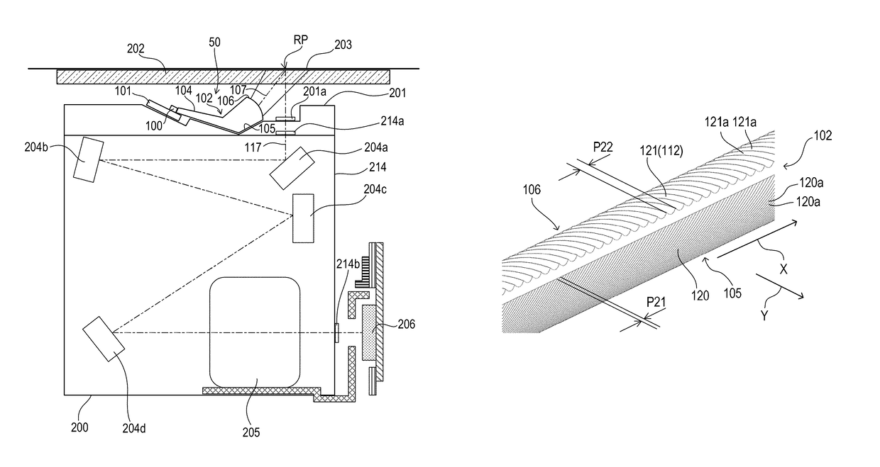
[0034]FIG. 5 is a cross-sectional view of an image reading apparatus 207 according to the first embodiment. The image reading apparatus 207 includes a main body 208, a platen glass 202 arranged on an upper portion of the main body 208, and an optical unit 200 movable in a sub-scanning direction Y inside the main body 208. The optical unit 200 is supported by a track 209 formed in the main body 208. The optical unit 200 is fixed to a belt 210 looped around a pair of pulleys 211 and 212. A motor 213 causes the pulley 211 to rotate forward and backward, to thereby rotate the belt 210 in directions indicated by the arrows C1 and C2. When the belt 210 is rotated forward by the motor 213 in the direction indicated by the arrow C1, the optical unit 200 moves along the track 209 in the sub-scanning direction Y. On the other hand, when the belt 210 is rotated backward by the motor 213 in the direction indicated b...

second embodiment

[0058]Next, a second embodiment will be described. In the second embodiment, the same components as those of the first embodiment are denoted by the same reference symbols and their description is omitted. An image reading apparatus, an optical unit, and an illumination device according to the second embodiment are the same as those according to the first embodiment and their description is omitted. A light guide according to the second embodiment will be described below.

[0059](Light Guide)

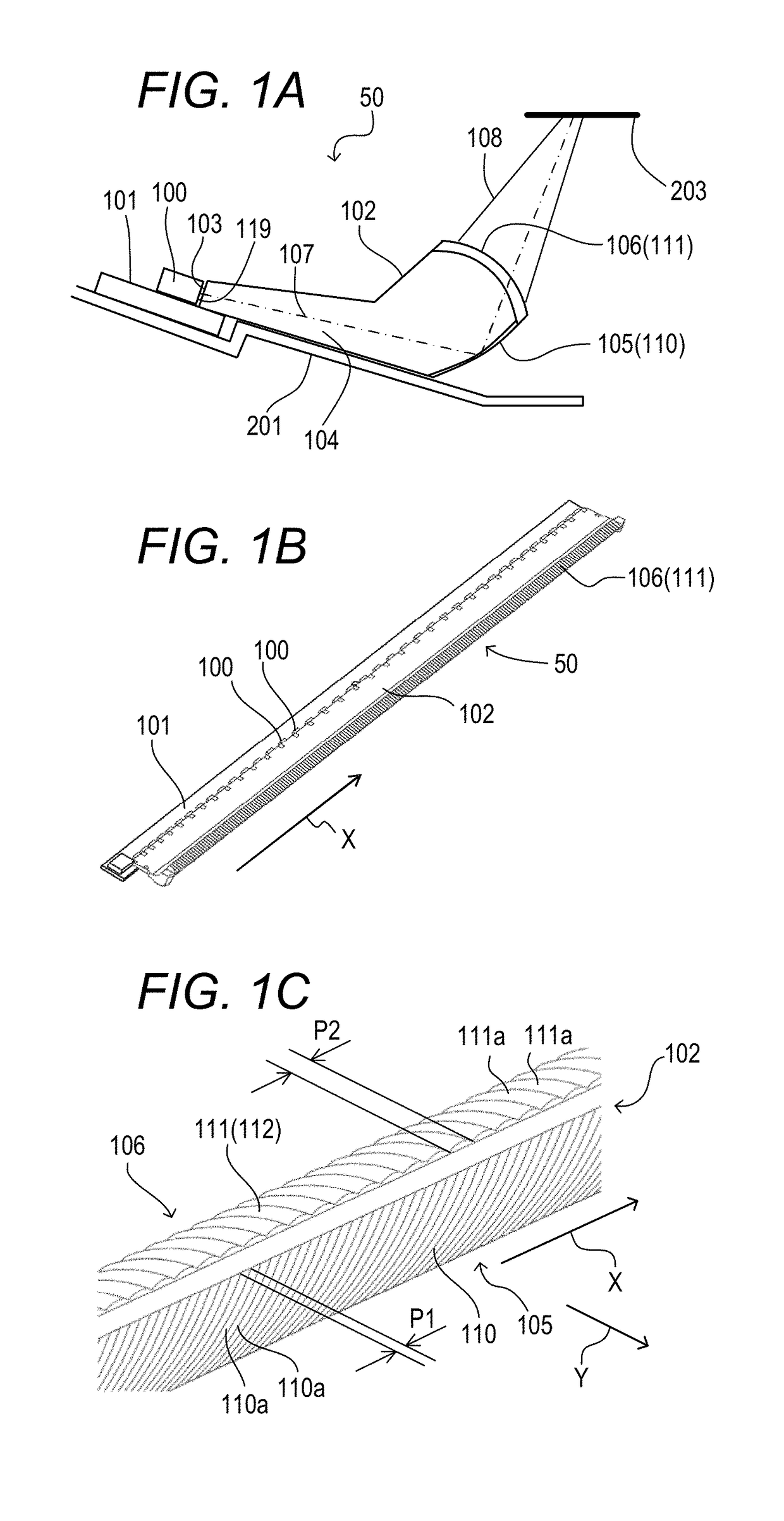
[0060]FIG. 6A and FIG. 6B are views for illustrating the illumination device 50 according to the second embodiment. FIG. 6A is a cross-sectional view for illustrating a sub-scanning cross-section of the illumination device 50. FIG. 6B is a partially enlarged view of the deflection surface 105 and the emission surface 106 of the light guide 102. A plurality of curved optical surfaces 120a and 121a are formed on the deflection surface 105 and the emission surface 106 side by side in the longitudinal...

third embodiment

[0068]Next, a third embodiment will be described. In the third embodiment, the same components as those of the first embodiment are denoted by the same reference symbols and their description is omitted. An image reading apparatus, an optical unit, and an illumination device according to the third embodiment are the same as those according to the first embodiment and their description is omitted. A light guide according to the third embodiment will be described below.

[0069](Light Guide)

[0070]FIG. 7A and FIG. 7B are views for illustrating the illumination device 50 according to the third embodiment. FIG. 7A is a cross-sectional view for illustrating a sub-scanning cross-section of the illumination device 50. FIG. 7B is a partially enlarged view of the deflection surface 105 and the emission surface 106 of the light guide 102. A plurality of curved optical surfaces 130a and 131a are formed on the deflection surface 105 and the emission surface 106 side by side in the longitudinal dire...


PUM


Abstract

An image reading apparatus including: an illumination device configured to illuminate an original; and a solid-state image sensor configured to receive and convert a reflected light from the original into an image signal, wherein the illumination device includes: a plurality of light emitting elements; and a light guide configured to guide light emitted from the light emitting elements toward the original, wherein the light guide includes: a deflection surface configured to deflect the light emitted from the light emitting elements to direct the light toward the original; and an emission surface configured to emit the light deflected by the deflection surface toward the original, wherein the deflection surface has a plurality of first curved optical surfaces provided side by side in a longitudinal direction of the light guide, and wherein the emission surface has a plurality of second curved optical surfaces provided side by side in the longitudinal direction.

Description

BACKGROUND OF THE INVENTION[0001]Field of the Invention[0002]The present invention relates to an image reading apparatus including an illumination device configured to illuminate an original.[0003]Description of the Related Art[0004]Hitherto, an image reading apparatus has been used in a copying machine, an image scanner, a multifunction printer, and the like. The image reading apparatus is configured to read an image of an original by illuminating the original with light and receiving light reflected from the original. The image reading apparatus includes an illumination device configured to illuminate an original with light. There is known an illumination device including a light guide configured to guide light emitted from a plurality of light emitting elements to an original (U.S. Pat. No. 8,876,355).[0005]FIG. 8A and FIG. 8B are views for illustrating a conventional illumination device 550. FIG. 8A is a perspective view of the illumination device 550. FIG. 8B is a cross-section...

Claims


Application Information

Patent Timeline
Patent Type & Authority Patents(United States)
IPC IPC(8): H04N1/04H04N1/028
CPCH04N1/0289H04N1/02885H04N1/02855
Inventor TAKAHASHI, TOSHIO
Owner CANON KK
Why Eureka
Try Eureka