Vacuum generating apparatus and vacuum tube lifter having a vacuum generating apparatus

a vacuum generating apparatus and vacuum tube technology, applied in the direction of manipulators, liquid fuel engines, gripping heads, etc., can solve the problems of high cost and technical complexity of measures, and achieve the effect of improving the holding power of the vacuum tube lifter, improving the security of the hold, and high volume flow

Active Publication Date: 2016-09-22
J SCHMALZ GMBH
View PDF6 Cites 32 Cited by
  • Summary
  • Abstract
  • Description
  • Claims
  • Application Information

AI Technical Summary

Benefits of technology

[0027]The evacuation of the lifting tube, preferentially by means of the primary vacuum generator, thereby results. In this process large flow volumes can occur, and in principle can be exhausted in an advantageous manner by the primary vacuum generator. The primary vacuum generator can be arranged, for example, in the area of the end of the lifting tube that faces away from the vacuum gripping device, for example on a bearing structure of the vacuum tube lifter. The ejector apparatus can be arranged, for example, in the area of the vacuum gripping device or on the vacuum gripping device itself. Thus the vacuum is first increased at a place where it is required for holding the object. The holding power of this vacuum tube lifter is thereby increased and the security of the hold is improved. The advantages according to the invention, in particular the combination of a highly useful volume flow and an increased vacuum level, are therefore utilized in an especially advantageous manner when the vacuum generating apparatus is used in a vacuum tube lifter.

Problems solved by technology

Such measures are often technically complex and expensive.

Method used


Image

  • Vacuum generating apparatus and vacuum tube lifter having a vacuum generating apparatus
  • Vacuum generating apparatus and vacuum tube lifter having a vacuum generating apparatus
  • Vacuum generating apparatus and vacuum tube lifter having a vacuum generating apparatus

Examples


Embodiment Construction

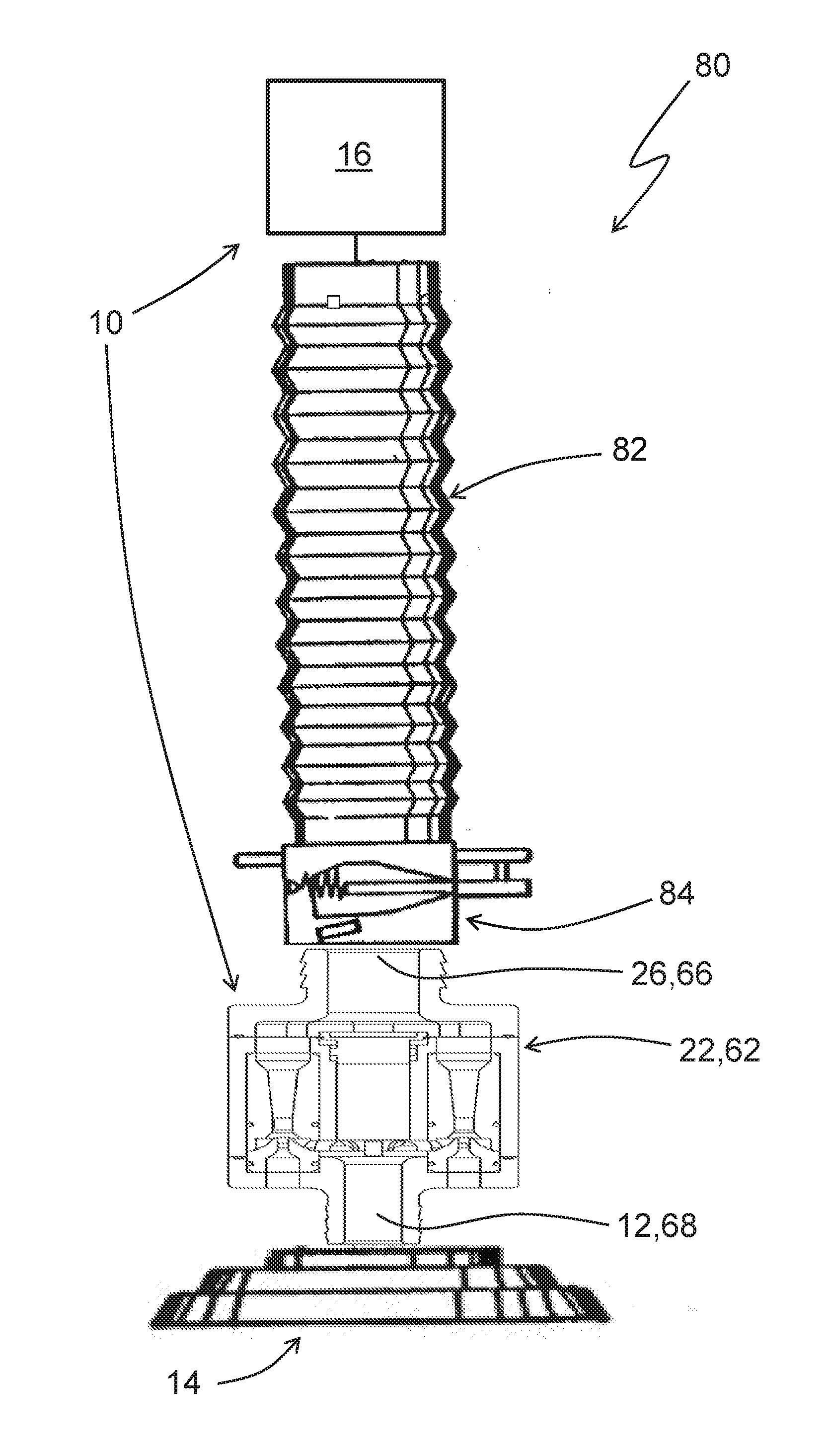
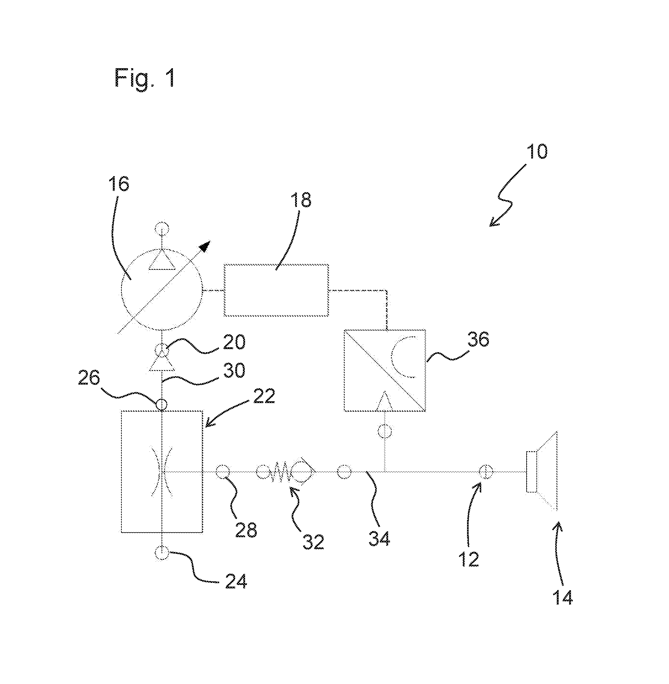
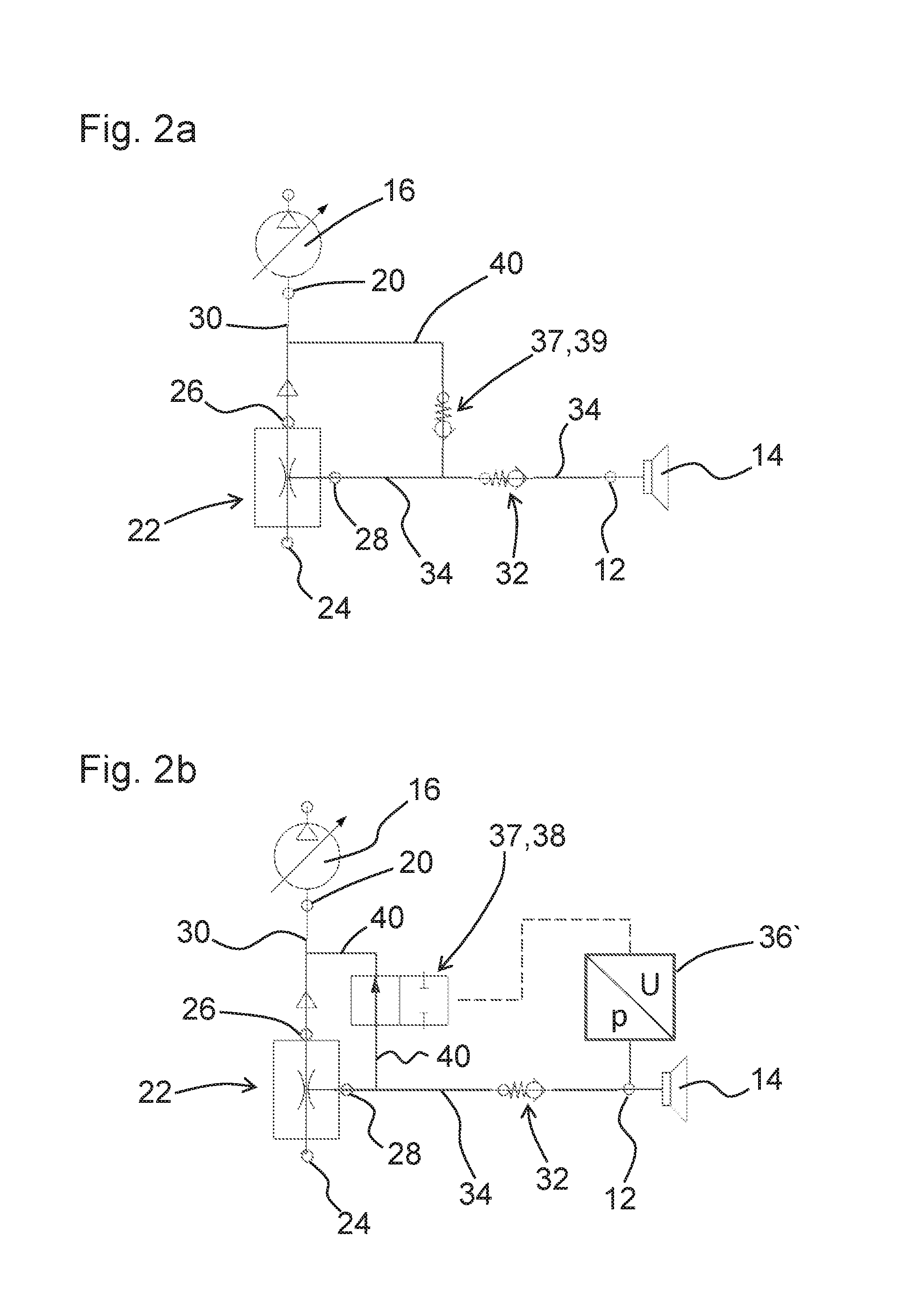
[0037]FIG. 1 schematically shows a connection diagram of a vacuum generating apparatus 10, which is connected via its user connection 12 to a vacuum handling device (here the suction gripper 14) which it supplies with a vacuum. A primary vacuum generator 16 in the illustrated example is embodied as an electrically driven vacuum pump. For controlling the primary vacuum generator, a control device 18 can be provided, by means of which, for example, the rotational speed of the vacuum generator 16 and / or its activation or deactivation can be controlled.

[0038]The vacuum generator 16 has a suction connection 20 through which a primary suction flow can be suctioned up. The primary suction flow drives an ejector apparatus 22. This has an inflow opening 24 and an outflow opening 26. The outflow opening 26 is open to the environment to the extent that environmental air can flow through said opening into the ejector 22 (unless a controlled closure takes place, see below). The ejector apparatus...


PUM


Abstract

The invention involves a vacuum generator apparatus with an electrically driven primary vacuum generator with a suction connection for sucking in a primary suction flow, and with at least one ejector apparatus, which has an inflow opening open to the environment, an outflow opening, and a suction opening that can be streamed through by a suction stream created at the suction opening from the inflow opening to the outflow opening, whereby the suction connection of the electrically driven primary vacuum generator is connected by flow with the outflow opening of the ejector apparatus.

Description

CROSS-REFERENCE TO RELATED APPLICATIONS[0001]This application claims benefit to German patent application serial no. 10 2015 202 603.5, filed 12 Feb. 2015, which is incorporated by reference in their entirety.BACKGROUND OF THE INVENTION[0002]1. Field of Invention[0003]The invention relates to a vacuum generating apparatus with an electrically driven primary vacuum generator, and a vacuum tube lifter with such a vacuum generating apparatus.[0004]2. Description of Related Art[0005]These vacuum generating apparatuses are used particularly when larger flow volumes of suctioned in air must be evacuated. One example is the handling of objects with what are called vacuum tube lifters. These permit handling in a way that the object to be gripped is held by a gripping device located on a lifting tube, and the lifting tube is shortened by the vacuum that is applied to it. Large volumes must therefore be regularly evacuated from the lifting tube. At the same time it is desirable to provide a s...

Claims


Application Information

Patent Timeline
Patent Type & Authority Applications(United States)
IPC IPC(8): B25J15/06F04D25/06F04D25/16F04D29/28
CPCB25J15/0675F04D25/16F04D25/06F04D29/281F04F5/52
Inventor KUOLT, HARALDGAUSS, JAN
Owner J SCHMALZ GMBH
Why Eureka
Try Eureka