Drive Mechanism for a Needle Insertion Arrangement

a technology of a drive mechanism and a needle insertion arrangement, which is applied in the direction of intravenous devices, injection syringes, automatic syringes, etc., can solve the problems of presenting a number of risks and challenges for users and healthcare professionals, and achieve the effect of improving the drive mechanism

Inactive Publication Date: 2016-09-29
SANOFI AVENTIS DEUT GMBH
View PDF3 Cites 5 Cited by
  • Summary
  • Abstract
  • Description
  • Claims
  • Application Information

AI Technical Summary

Benefits of technology

[0004]It is an object of the present invention to provide...

Problems solved by technology

Administering an injection is a process which presents a number of risks and challenges for users and healthcare professionals, both mental and physical.
During manual insertion o...

Method used


Image

  • Drive Mechanism for a Needle Insertion Arrangement
  • Drive Mechanism for a Needle Insertion Arrangement
  • Drive Mechanism for a Needle Insertion Arrangement

Examples


Embodiment Construction

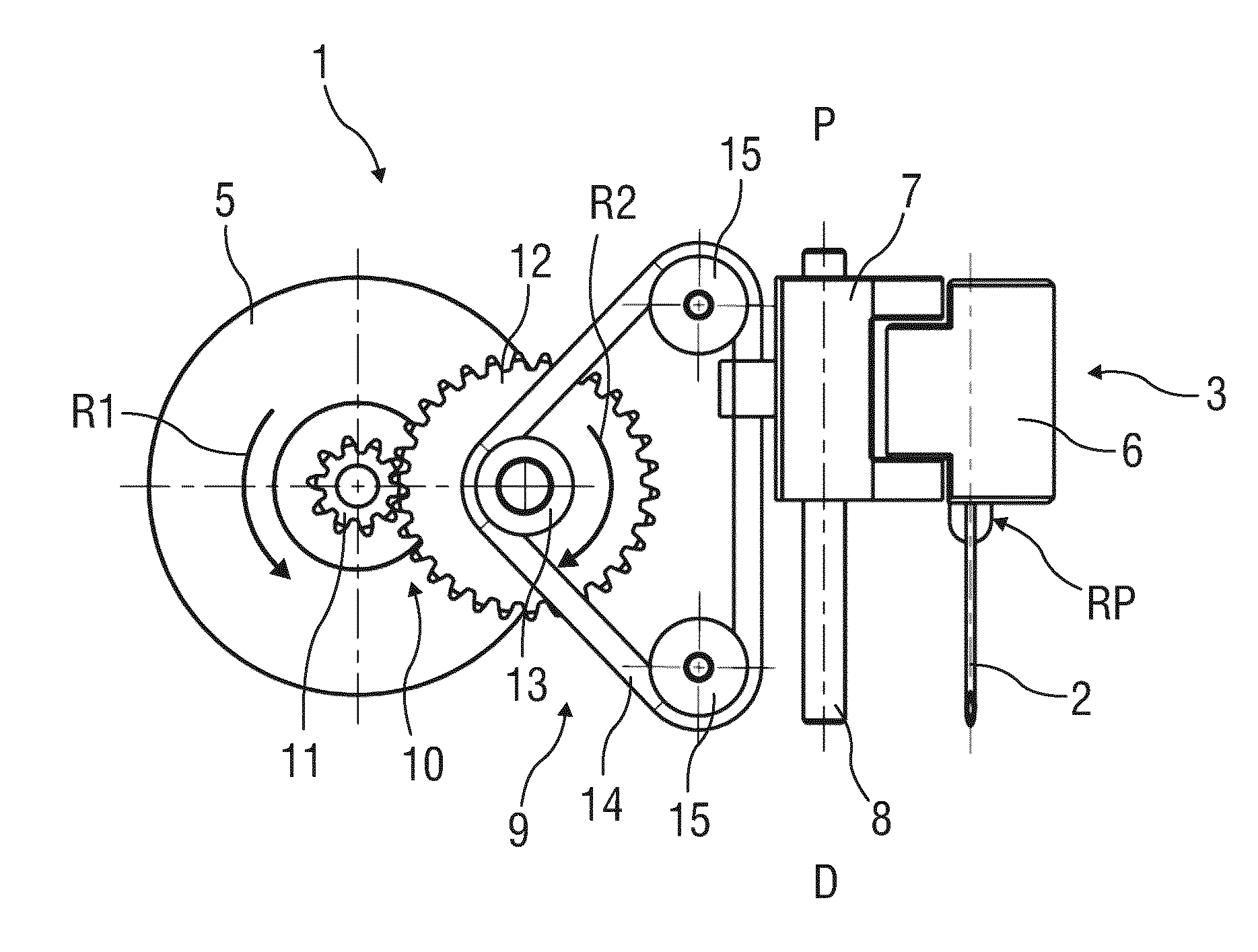
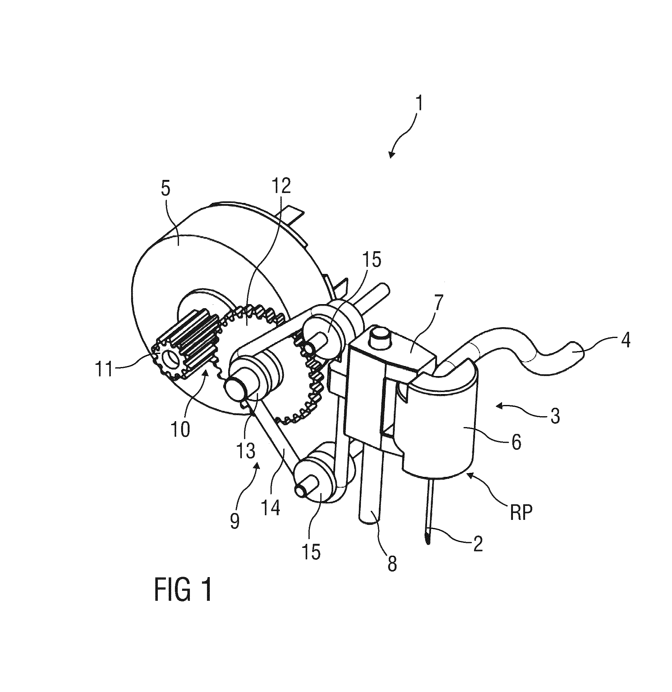
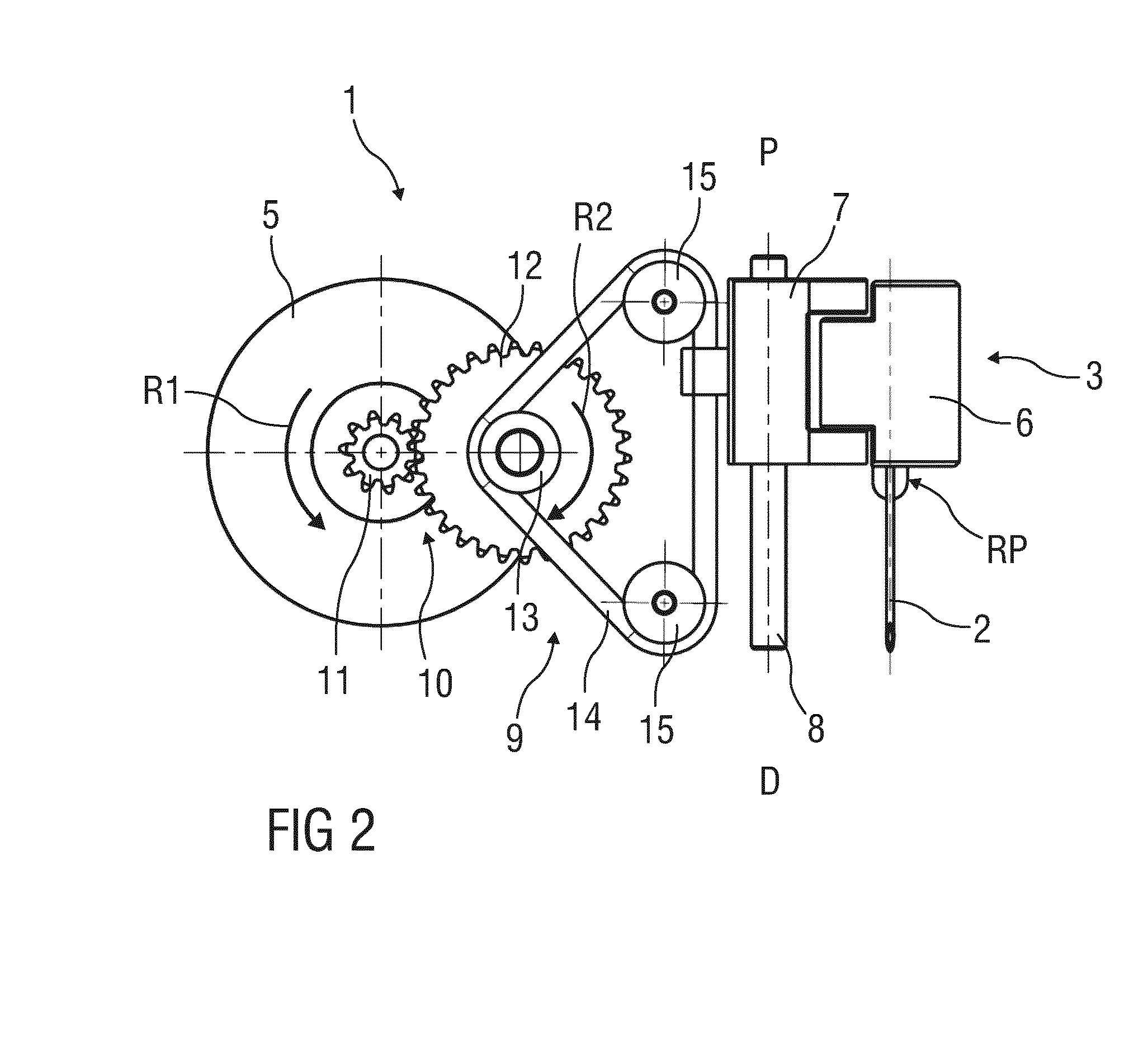
[0028]FIG. 1 is a schematic perspective view of an exemplary embodiment of an insertion arrangement 1 for automatically or semi-automatically inserting an injection needle 2 into an injection site. The arrangement 1 may be applied in medicament pumps, e.g. insulin pumps which may be permanently worn on the body.

[0029]The injection needle 2 is part of a disposable unit 3, further comprising a tube 4 for establishing a fluid communication of the needle 2 with a drug container (not illustrated) and comprising a needle base 6, to which the injection needle 2 may be fixed for mechanically connecting the needle 2 to a drive mechanism 9 of an injection unit (not illustrated). The needle base 6 is inserted in a forked needle retainer 7 which is arranged to be moved up and down in a linear guide 8. This linear movement corresponds to insertion of the needle 2 into the injection site, e.g. subcutaneous body tissue and removal from the injection site, respectively.

[0030]The drive mechanism 9 f...


PUM


Abstract

The invention relates to a drive mechanism for a needle insertion arrangement, the drive mechanism comprising: an actuator, a rotatable drive pulley directly or indirectly coupled to the actuator, and a belt adapted to engage the drive pulley and adapted to be fixed to a needle retainer.

Description

TECHNICAL FIELD[0001]The invention relates to a drive mechanism for a needle insertion arrangement.BACKGROUND OF THE INVENTION[0002]Administering an injection is a process which presents a number of risks and challenges for users and healthcare professionals, both mental and physical. During manual insertion of an injection needle into an injection site, e.g. the skin of a patient, it may be difficult to avoid tilting and bending of the needle and the insertion may be slow thus causing pain.[0003]There remains a need for an improved drive mechanism for a needle insertion arrangement.SUMMARY OF THE INVENTION[0004]It is an object of the present invention to provide an improved drive mechanism for a needle insertion arrangement[0005]The object is achieved by a drive mechanism for a needle insertion arrangement according to claim 1.[0006]Exemplary embodiments of the invention are given in the dependent claims.[0007]According to the invention a drive mechanism for a needle insertion arra...

Claims


Application Information

Patent Timeline
IPC IPC(8): A61M5/20
CPCA61M2005/206A61M5/20A61M5/3287A61M5/46
Inventor SCHABBACH, MICHAELWERNER, MEINOLFZECKAI, OLAFNZIKE, PHILIPPE
Owner SANOFI AVENTIS DEUT GMBH
Why Eureka
Try Eureka