Dental bite block assembly

a technology of dental bite and assembly, which is applied in the field of dental treatment devices, can solve the problems of patient tongue being at risk of injury, restricted physical access, and long dental procedures,

Active Publication Date: 2016-10-27
ASCENTCARE DENTAL PROD INC
View PDF25 Cites 21 Cited by
  • Summary
  • Abstract
  • Description
  • Claims
  • Application Information

AI Technical Summary

Problems solved by technology

Dental procedures often require a dentist and / or dental hygienist to work under numerous limitations, primarily among them being restricted physical access available for performing dental procedures within a patient's mouth and limited ambient light.
In addition, again especially during dental procedures that employ high speed drills, the patient's tongue is at risk of injury if left unrestrained, which may also require the assistance of a dental assistant.
Further, dental procedures can also be lengthy.
A patient's masseter, temporalis, medial pterygoid and lateral pterygoid muscles can become tired or sore when the patient's mouth has been open for long periods of time.
Prior attempts to alleviate the fatigue that patients experience during dental procedures, however, tend to aggregate the limitations noted above and to further obstruct physical access to the interior of the mouth, interfering with the ability of the dentist or dental hygienist to perform certain dental procedures and limiting light.
Further, some prior attempts to relieve fatigue were designed solely for the left or right side of the mouth, limiting their usefulness.
In those devices that held a dental accessory, such as a saliva ejection tube, the dental accessary was also difficult to install and required the use of both hands or the complete removal of the device from the patient's mouth to attach and remove the dental accessory.
In the case of saliva ejection tubes, such devices were further designed to hold but one type or size of saliva ejection tube and lacked the ability or hold different sized saliva ejection tubes.
In addition, sterilization and reuse was problematic because of cracks and crevices in many prior designs.
Prior attempts to alleviate fatigue usually added further obstruction, limiting access for the performance of dental procedures and typically required the use of two hands or a dental assistant to attach or remove a dental accessary, such as a light source, saliva ejection tube holder, and / or tongue suppressor.

Method used


Image

  • Dental bite block assembly
  • Dental bite block assembly
  • Dental bite block assembly

Examples


first embodiment

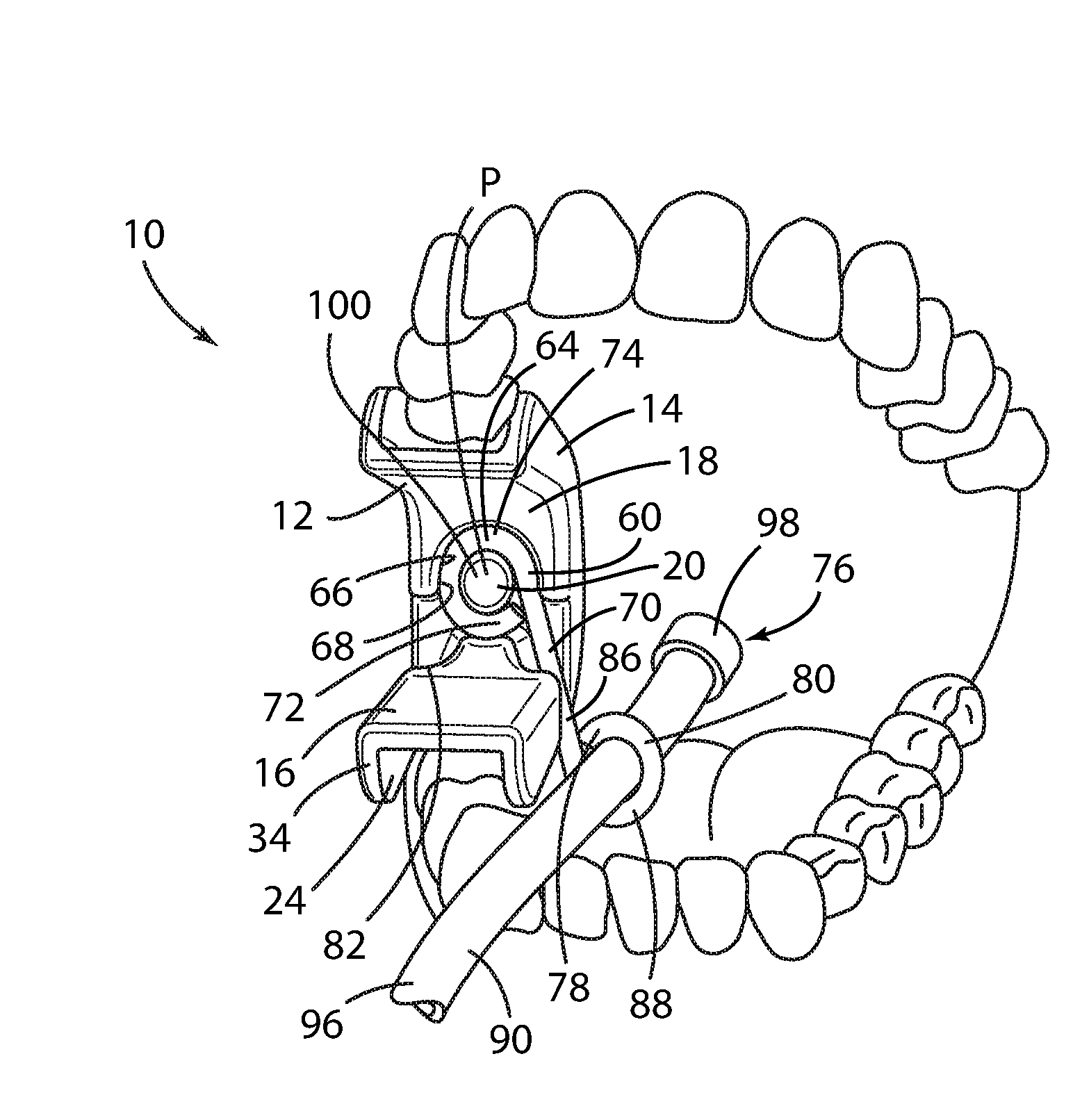
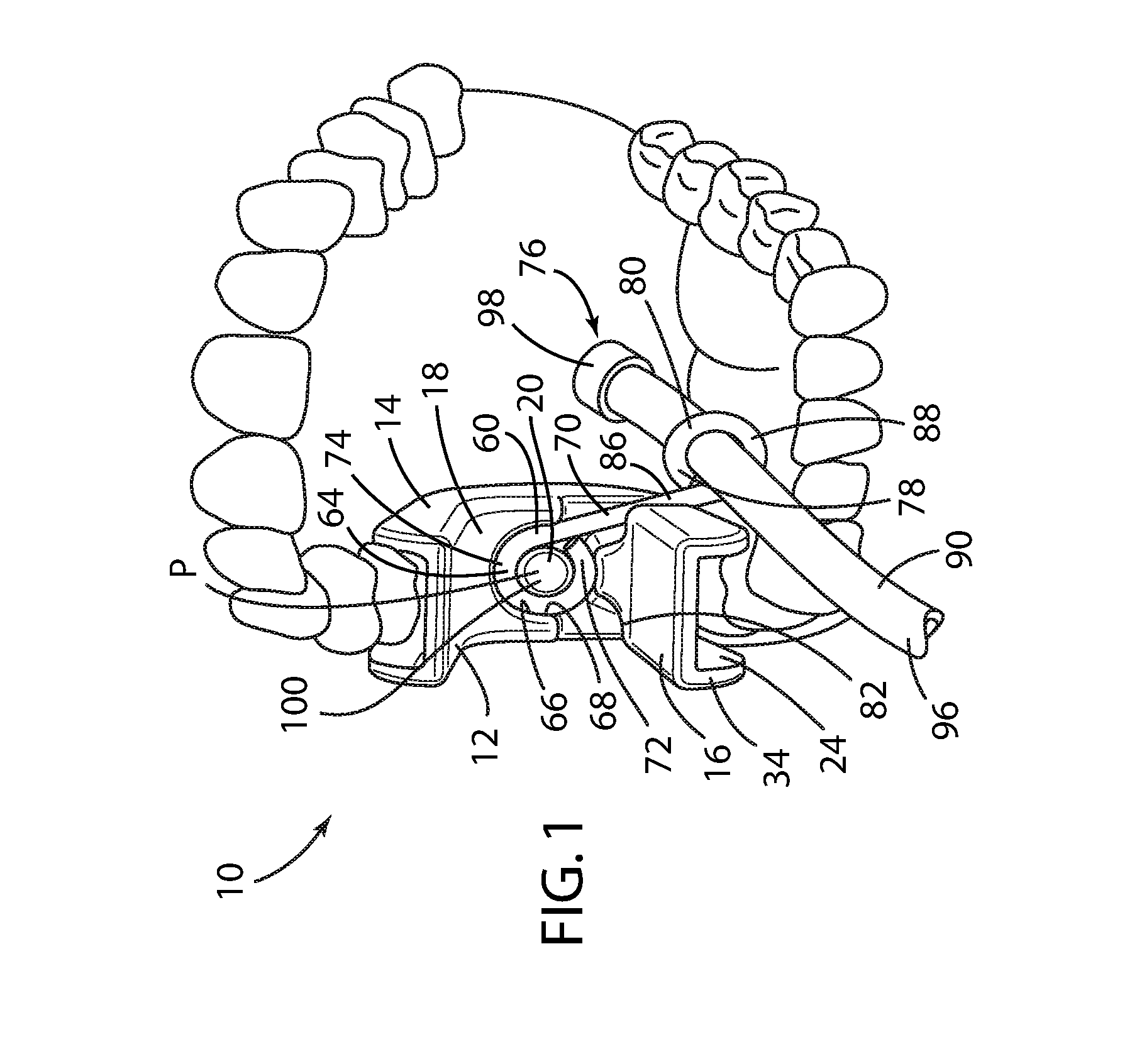
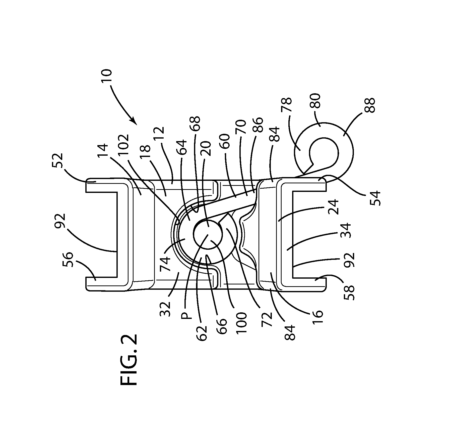
[0052]In the dental accessory 60 in accordance with the present disclosure, the accessory mount 20 includes a circular recess 66 preferably formed in the shape of the torus 68 concentrically disposed proximate the first magnetically energetic material 22. In this embodiment, the dental accessory 60 is fabricated of a steel metal wire 70 as the second magnetically energetic material 64. The steel wire 70, comprising a ferromagnetic material, has a first distal end 72 having a curved portion 74 for receiving a dental tool 76 and a second distal end 78 having a curved portion 80 that forms the dental bite block mount 62 and which is fittingly received within the torus 68 disposed upon the exterior surface 32 of the central portion 18 of the U-shaped mounting base 12. Preferably, the outer diameter of the curved portion 80 of the second distal end 78 of the dental accessory 60 is only marginally smaller than the inner diameter of the torus 68, thereby providing a snug and secure fit the...

second embodiment

[0069]For example, a second dental accessory 110 is shown in FIGS. 7 and 8. In this embodiment, an accessory mount 112 is similarly disposed on the central portion 18 of the U-shaped mounting base 12, but in this case comprises a forwardly facing recess 114 is disposed proximate the first magnetically energetic material 22 embedded in the central portion 18. The dental bite block mount 116 of the dental accessory 110 in this embodiment comprises a rearwardly facing member 118 within which the second magnetically energetic material 64 is disposed, wherein the rearwardly facing member 118 of the second dental accessory 110 is fittingly received within the forward facing recess 114 of the central portion 18 of the U-shaped mounting base 12. Preferably, in this embodiment, both the first and the second magnetically energetic materials 22, 64 in the central portion 18 of the U-shaped mounting base 12 and the second dental accessory 110, respectively, are both a permanent magnet formed of...


PUM


Abstract

A dental bite block assembly includes a U-shaped mounting base having an upper bite portion, a lower bite portion, a central portion, an accessory mount, and a first magnetically energetic material embedded in the central portion of the U-shaped mounting base proximate the accessory mount. A dental accessory has a dental bite block mount that is detachably coupled with the accessory mount of the U-shaped mounting base and a second magnetically energetic material disposed in the dental accessory proximate the dental bite block mount. When the dental bite block mount is coupled with the accessory mount, the first magnetically energetic material embedded in the central portion of the U-shaped mounting base and the second magnetically energetic material disposed in the dental accessory are in operable magnetic engagement with each other.

Description

CROSS-REFERENCE TO RELATED APPLICATION AND CLAIM TO PRIORITY[0001]The present application claims priority under 35 U.S.C. §119(e) of U.S. Provisional Application 62 / 150,448, filed Apr. 21, 2015, the entire disclosure of which is incorporated herein by reference.FIELD OF THE INVENTION[0002]The present invention generally relates to a dental treatment device, and more particularly, to a dental bite block assembly that is adapted to accept and interact with dental treatment accessories.BACKGROUND OF THE INVENTION[0003]Dental procedures often require a dentist and / or dental hygienist to work under numerous limitations, primarily among them being restricted physical access available for performing dental procedures within a patient's mouth and limited ambient light. For example, during dental procedures that employ high speed drills, the patient's mouth must receive the dental drill unit and a saliva ejection tube to evacuate particulates and / or saliva from the patient's mouth during the...

Claims


Application Information

Patent Timeline
Patent Type & Authority Applications(United States)
IPC IPC(8): A61C5/00A61C1/14A61B13/00A61C17/06A61C1/08
CPCA61C5/007A61C17/043A61C1/14A61B13/00A61C1/088A61B1/06A61B1/24A61B1/32A61B90/16A61C17/08
Inventor RITTER, AUSTIN RASMUSSEN
Owner ASCENTCARE DENTAL PROD INC
Why Eureka
Try Eureka