Object hanger hook with friction-increasing compression

Inactive Publication Date: 2016-11-17
LEAHY MARK ROBERT
View PDF1 Cites 5 Cited by
  • Summary
  • Abstract
  • Description
  • Claims
  • Application Information

AI Technical Summary

Benefits of technology

[0009]Solving the problems associated with “hanging something on a wall” is accomplished significantly by providing a hanger hook (open on both ends) that includes an internal compression force element that applies pressure in a mostly orthogonal direction to the force of gravity and increases stabilizing frictional forces that are on vertical interior surfaces (opposing to the compression force element surface) of the hanger hook. This hanger hook, among other benefits, helps stabilize, prevent or limit canting due to disturbing effects of minor forces in the surrounding environment that lead to misaligned pictures and items hung on or attached to a wall or vertical surface, and prevent unintentional disconnect.
[0010]The hanger hook includes effectively recessed fastener positions as to eliminate snagging, or otherwise mistakenly hanging an item on the nail (or other type of fastener used to secure a hanger or picture hook to a vertical surface) or an inappropriate part of a picture hanger hook. The recessed fastener aspect of the hanger hook eliminates the need to “look/reach behind the object” in order to make certain tha

Problems solved by technology

Many efforts have been made to solve the several problems that exist when attempting to “hang

Method used


Image

  • Object hanger hook with friction-increasing compression
  • Object hanger hook with friction-increasing compression
  • Object hanger hook with friction-increasing compression

Examples


Embodiment Construction

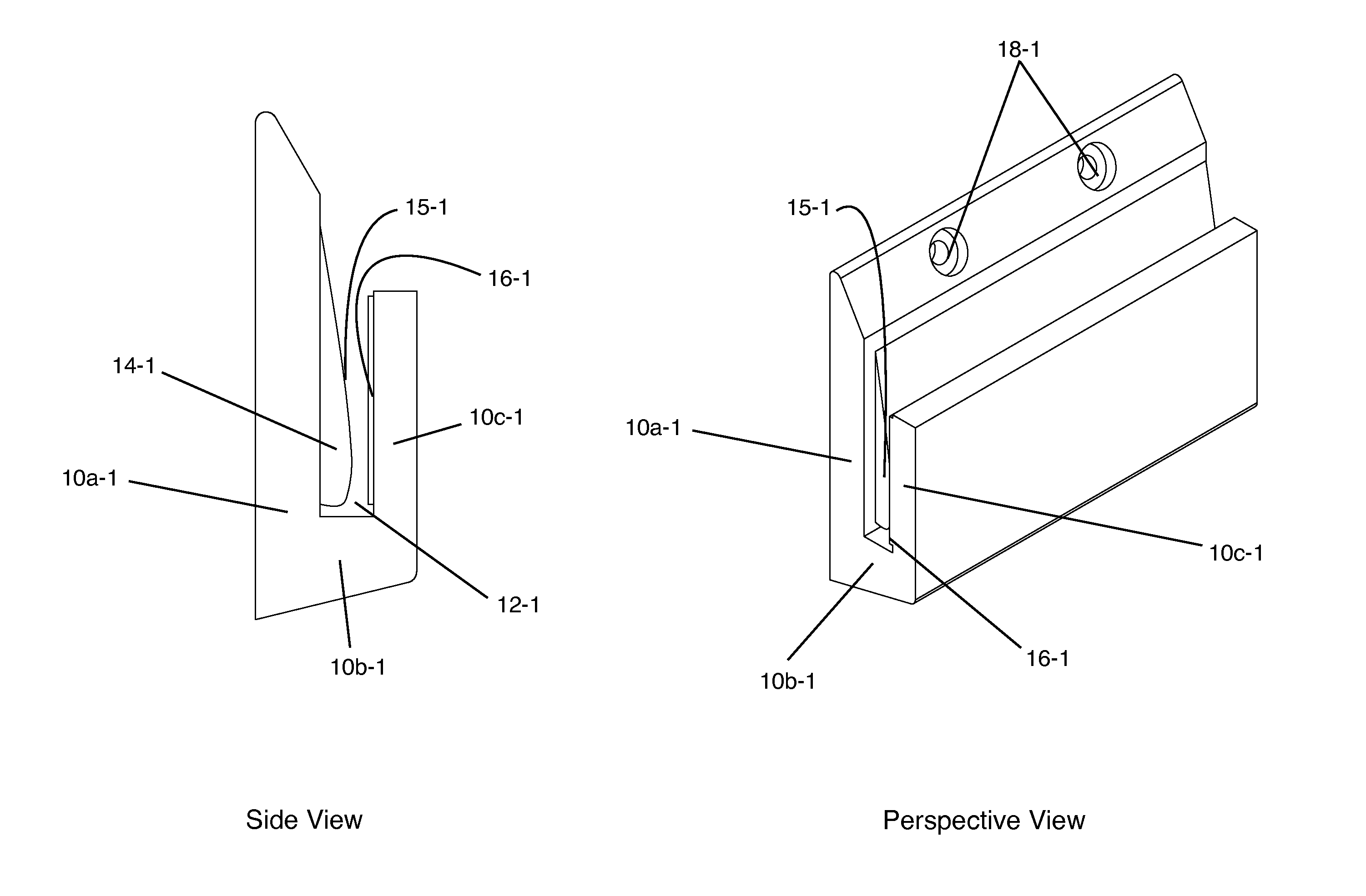
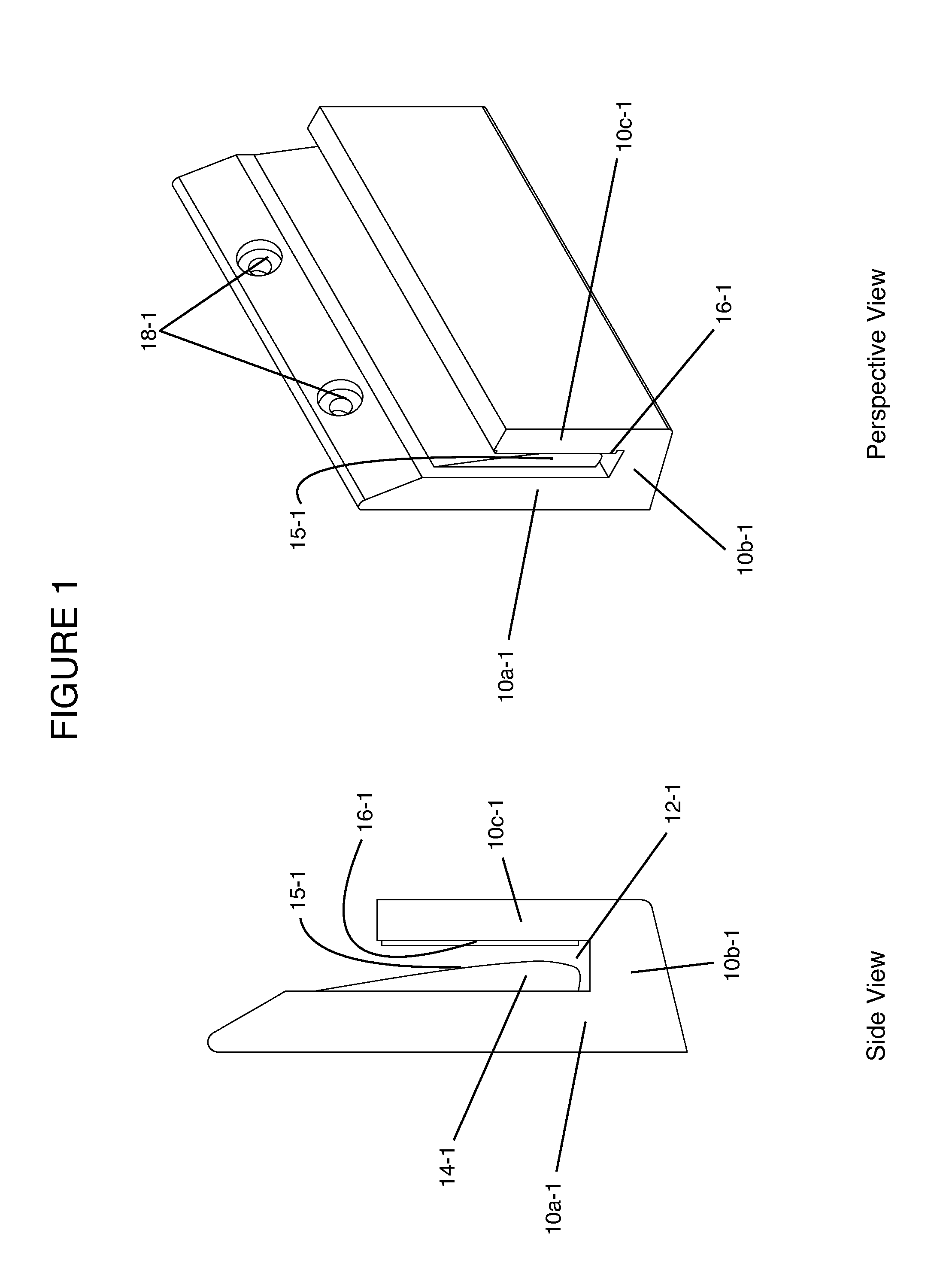
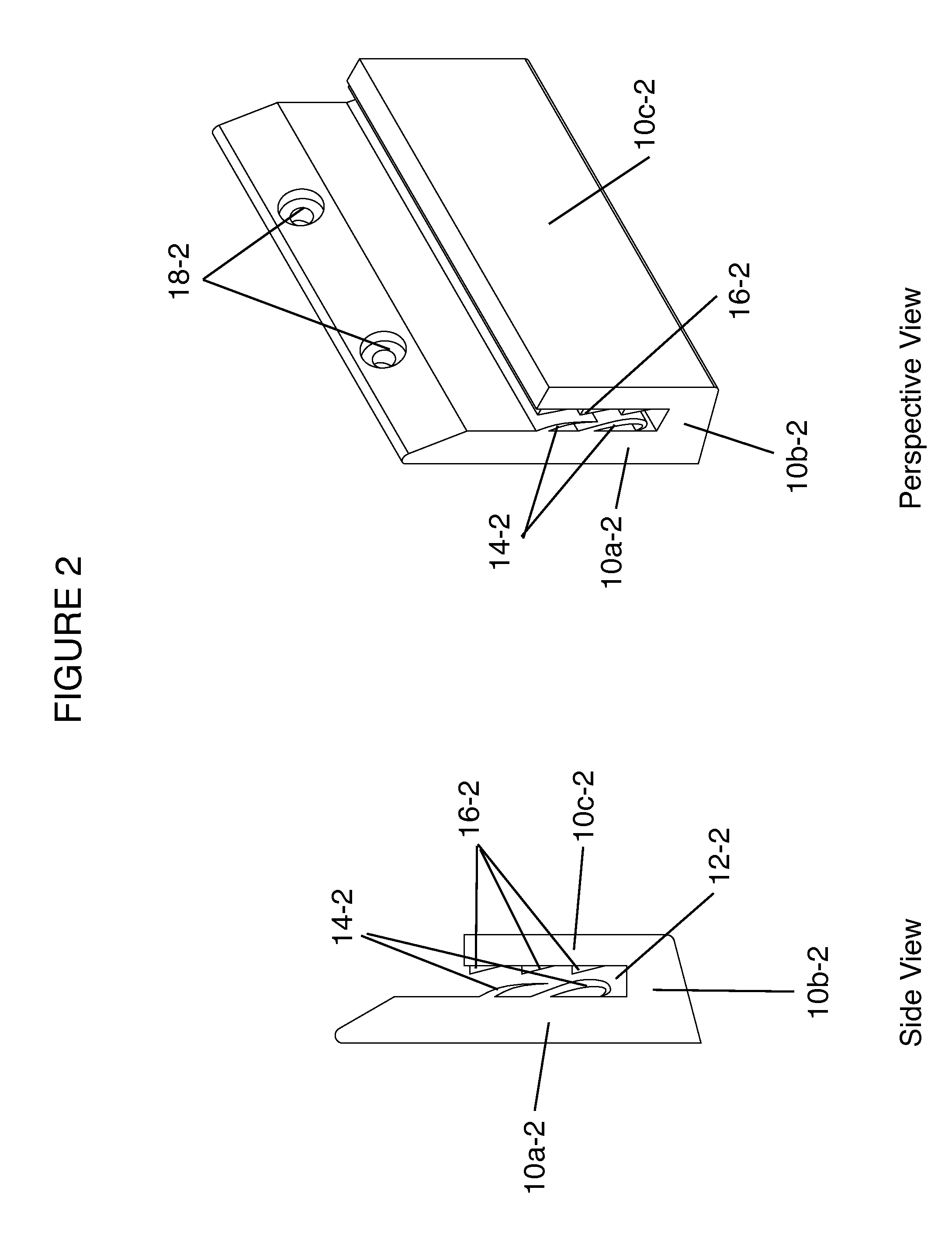
[0015]According to this invention, a hanger hook is provided with open sides, a vertical surface contacting hanger frame leg (e.g. 10a-1), an opposing hanger frame leg (e.g. 10c-1), and a connecting hanger frame base (e.g. 10b-1). Combining the hanger hook legs results in a hanger hook pocket (e.g. 12-1) that has generally right angle construction with a flat base. This generally flat base for the hanger hook pocket provides several benefits: (a) distribution of downward pressure, (b) the necessary space for compression element design and action, (c) opportunity for a customer to make subtle additions to the base and thereby raise an item being hung by the hanger hook without introducing destabilization.

[0016]The hanger hook may be attached (e.g. nailed, screwed, or by the use of similar means) to a vertical surface utilizing the recessed fastener holes (e.g. 18-1, 18-2, 18-3). The hanger hook can have as few as one fastener hole though embodiments using more fastener holes are envi...


PUM


Abstract

An object hanger hook for hanging an item, such as a picture, to a vertical or near vertical wall surface utilizing elements that provide internal, generally orthogonal forces against an opposing internal hook surface that help secure and level item to be hung. Embodiments are described each showing force elements and elements to make engagement or release of object hanger hook from item to be hung easy and adjustable.

Description

CROSS-REFERENCE TO RELATED APPLICATIONS[0001]This application claims the benefit of PPA application No. 61 / 992,058, filed May 12, 2014 by the present inventor, which is incorporated by reference.FEDERALLY SPONSORED RESEARCH[0002]None; no federally sponsored research was involved in this inventionNAMES OF PARTIES TO A JOINT RESEARCH AGREEMENT[0003]None; no joint research agreement associated with this inventionSEQUENCE LISTING[0004]None and not applicable to this inventionSTATEMENT REGARDING PRIOR DISCLOSURES BY AN INVENTOR OR JOINT INVENTOR[0005]Not applicable (i.e. no disclosures by inventor prior to PPA No. 61 / 992,058)BACKGROUND OF INVENTION[0006]Previously, numerous devices for positioning, securing, and otherwise hanging items to a vertical or near vertical surface, typically a wall, are known in the prior art. Many efforts have been made to solve the several problems that exist when attempting to “hang something on a wall,” an often frustrating, time consuming, and surprisingly...

Claims


Application Information

Patent Timeline
IPC IPC(8): A47G1/16F16M13/02
CPCF16M13/02A47G1/1613
Inventor LEAHY, MARK ROBERT
Owner LEAHY MARK ROBERT
Why Eureka
Try Eureka