Methods and apparatus to detect compound meter failure

a technology of compound meter and meter body, which is applied in the direction of volume metering, liquid/fluent solid measurement, instruments, etc., can solve the problems of underbilling, billing issue, and difficulty in determining whether a compound meter has failed, and/or potential dissatisfaction of utility customers

Inactive Publication Date: 2016-11-24
ITRON GLOBAL SARL
View PDF5 Cites 6 Cited by
  • Summary
  • Abstract
  • Description
  • Claims
  • Application Information

AI Technical Summary

Problems solved by technology

Compound utility meters often utilize multiple flow meters to more accurately measure a fluid at different flow rates due to limited accuracy ranges characteristic of flow meters.
It is sometimes difficult to determine whether a compound utility meter has failed until the resulting effects are severe (e.g., an outage, incorrect billing over a significant time duration, etc.).
For example, when a low flow rate flow is prevented from bypassing a high flow rate branch, the low flow rate flow may instead flow through the high flow rate branch, which may result in inaccurate measurements of the flow rate, thereby causing a billing issue (e.g., underbilling) and / or potential dissatisfaction of utility customers due to overbilling.
In other situations, a failure that prevents flow into a high flow rate branch of a compound utility meter may cause a reduced flow rate through a low flow rate branch (e.g., a low flow rate even during a time period with high flow rate demands), which can sometimes result from a small cross-sectional diameter of the low flow rate branch.
Such restricted flow can often result in outages.
Because compound utility meters may often fail unpredictably, they are often replaced based on a defined duration of time in the field (e.g., three years, several months, etc.), regardless of usage and / or condition of the compound utility meters, thereby resulting in higher replacement and / or part costs, even if the compound utility meters are operating normally.
Compound utility meters are often tested on test benches, however, such test benches often require removal of the meter, testing the meter, repair if necessary, and reinstalling the meter.

Method used


Image

  • Methods and apparatus to detect compound meter failure
  • Methods and apparatus to detect compound meter failure
  • Methods and apparatus to detect compound meter failure

Examples


Embodiment Construction

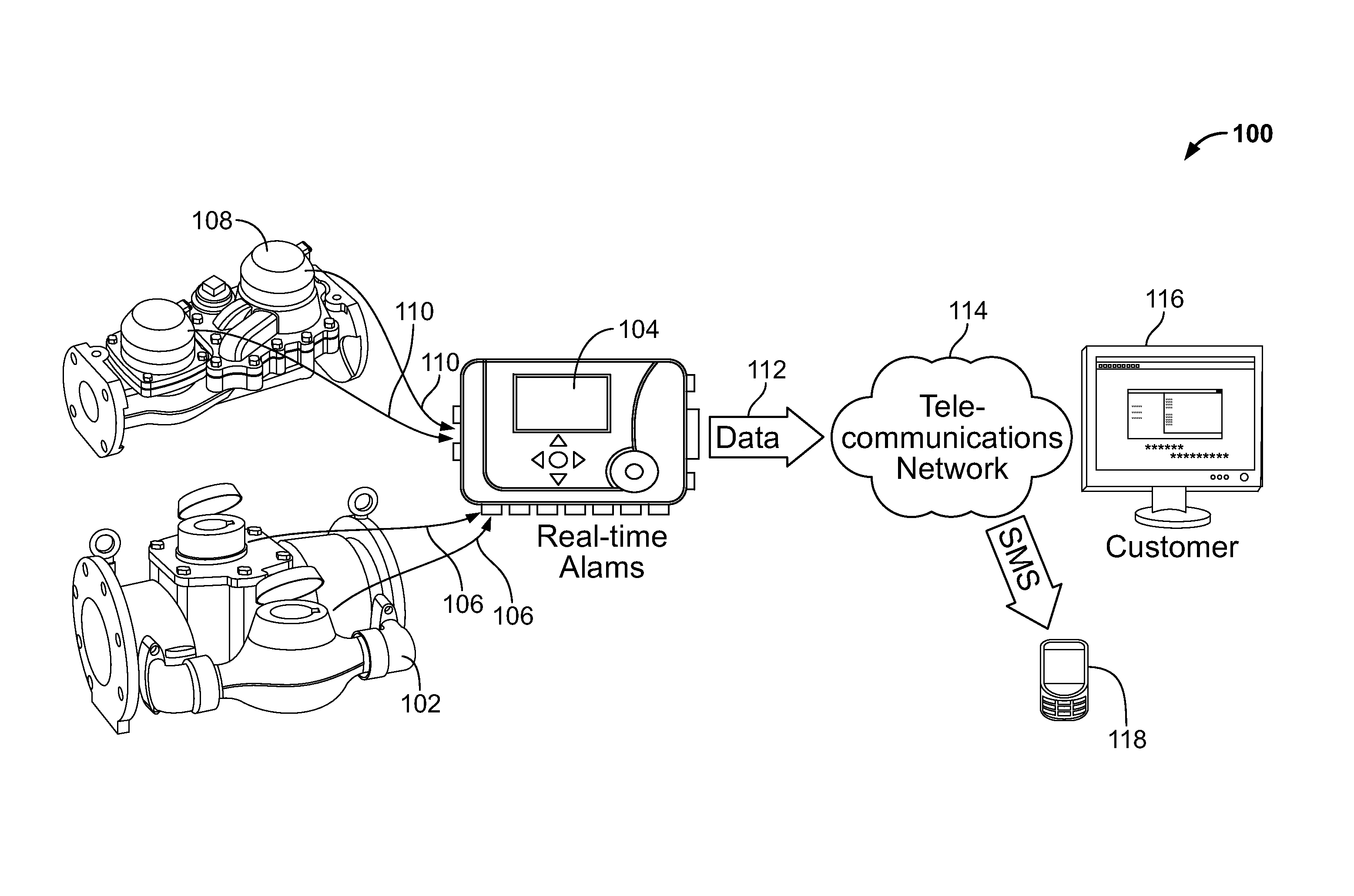
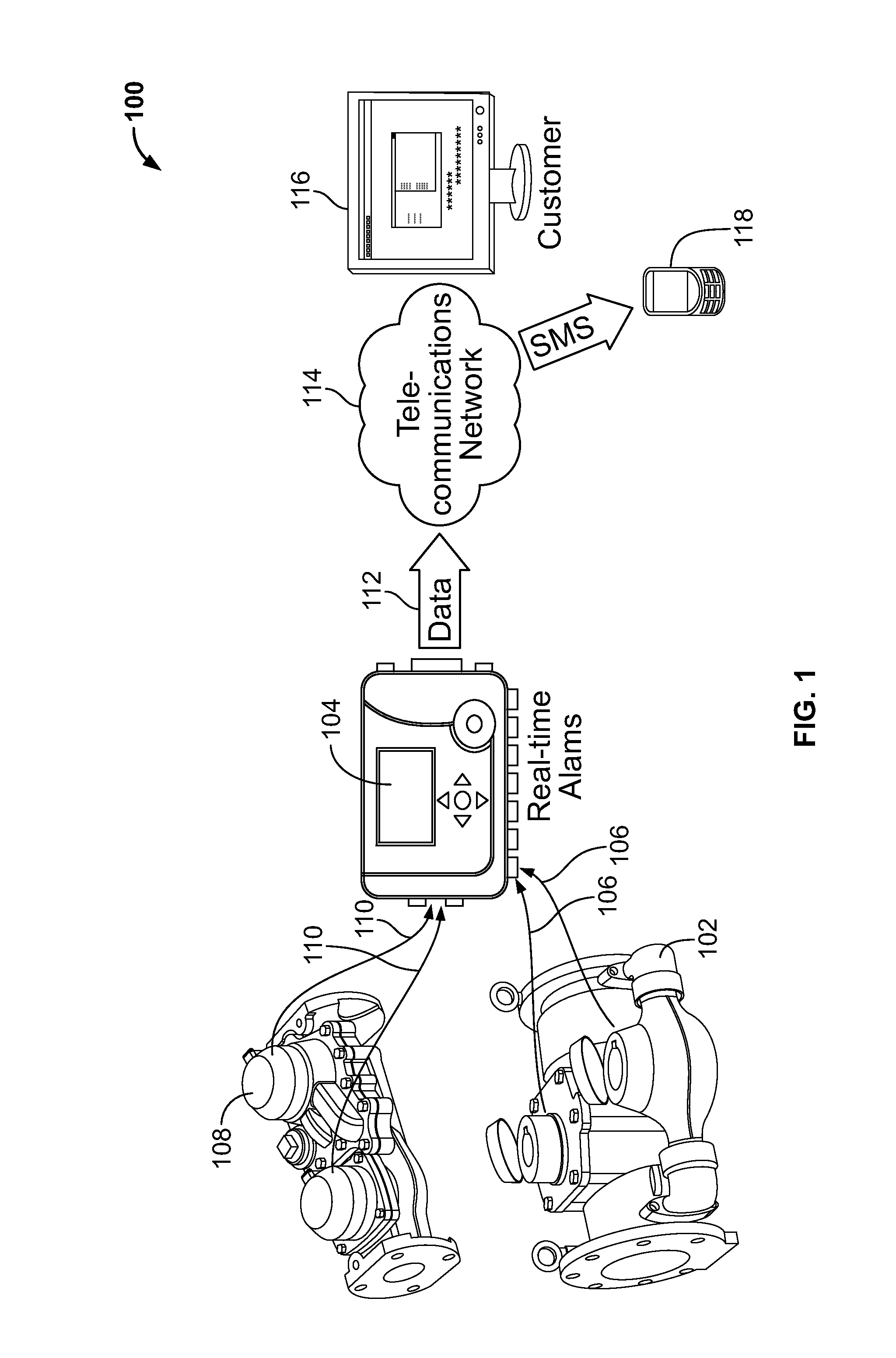
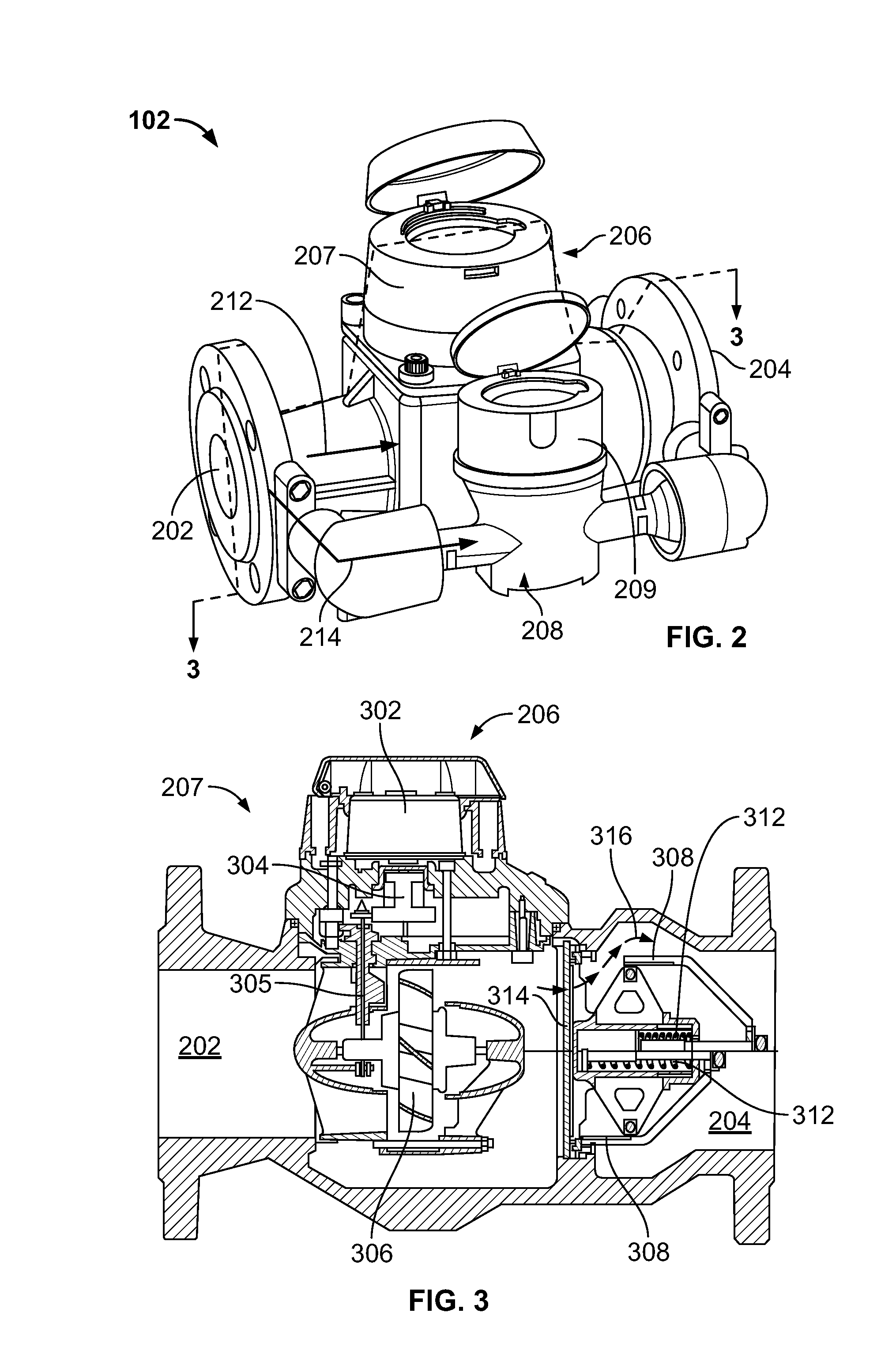
[0017]Methods and apparatus to detect compound meter are disclosed herein. Compound utility meters (e.g., compound meters, compound water meters, bypass water meters, etc.) are typically used to measure flow rates of water provided to residential and / or commercial areas or buildings. These compound utility meters typically use multiple flow meters to accurately measure flow consumption at different flow ranges and / or pressures (e.g., different flow regimes). In particular, compound utility meters usually have a high flow rate branch with a high flow rate meter and a low flow rate branch with a low flow rate meter. Typically, the high flow rate branch is bypassed and / or isolated in low flow rate conditions and the low flow rate branch is not bypassed in a high flow rate condition because a low cross-sectional diameter of the low flow rate branch still maintains a relatively low flow rate therethrough while the high flow rate branch accommodates the increased pressure of the high flow...


PUM


Abstract

Methods and apparatus to determine compound meter failure are disclosed. One disclosed example apparatus includes a receiver to receive fluid flow rate data from a first fluid flow rate meter on a first channel of a compound utility meter and a second fluid flow rate meter on a second channel of the compound utility meter. The example apparatus also includes a processor communicatively coupled to the receiver, where the processor is to determine a failure condition of the compound utility meter based on the flow rate data received from the first and second fluid flow rate meters.

Description

FIELD OF THE DISCLOSURE[0001]This disclosure relates generally to compound meters and, more particularly, to methods and apparatus to detect compound meter failure.BACKGROUND[0002]Compound meters (e.g., compound water meters, compound utility meters) are often used in, for example, commercial or home water utility systems to measure an amount of water provided and / or consumed in a building and / or an area. Compound utility meters often utilize multiple flow meters to more accurately measure a fluid at different flow rates due to limited accuracy ranges characteristic of flow meters. To accurately measure flow rates at different flow ranges, compound utility meters usually have a high flow rate flow meter on a high flow rate portion, or branch, of the utility meter and a low flow rate flow meter on a low flow rate portion, or branch, of the utility meter. Compound utility meters also typically include a bypass mechanism (e.g., a bypass valve, a commutation valve, a pressure valve, etc...

Claims


Application Information

Patent Timeline
Patent Type & Authority Applications(United States)
IPC IPC(8): G01F25/00G01F7/00
CPCG01F7/00G01F25/0007G01F15/005G01F15/063G01F15/10G01F15/185G01F25/10
Inventor SCHWEITZER, CHRISTOPHELEBRETON, THIBAUTBARLETTA, FLORIAN
Owner ITRON GLOBAL SARL
Why Eureka
Try Eureka