Reactor
a reactor and coil technology, applied in the field of reactors, can solve the problems of generating vibration and noise, affecting the reliability of the reactor, so as to achieve the effect of reducing the stress to be applied to the connection portion between the drawn portion and the terminal, suppressing vibration and noise, and high reliability
- Summary
- Abstract
- Description
- Claims
- Application Information
AI Technical Summary
Benefits of technology
Problems solved by technology
Method used
Image
Examples
first embodiment
1. First Embodiment
[0033](1) Structure
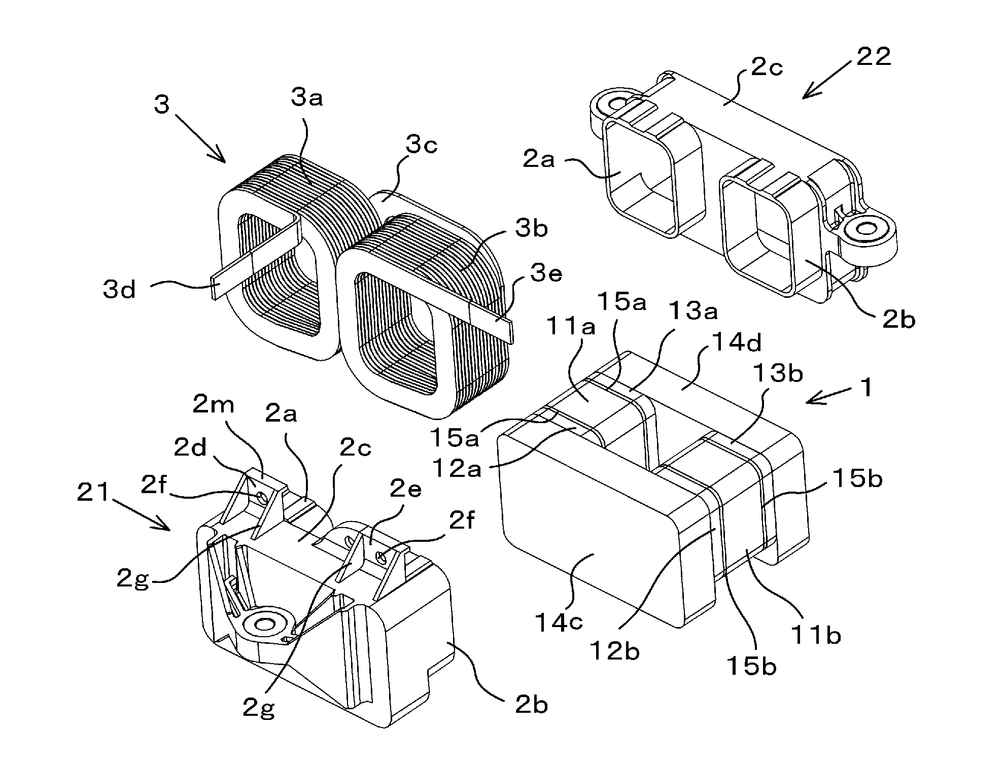
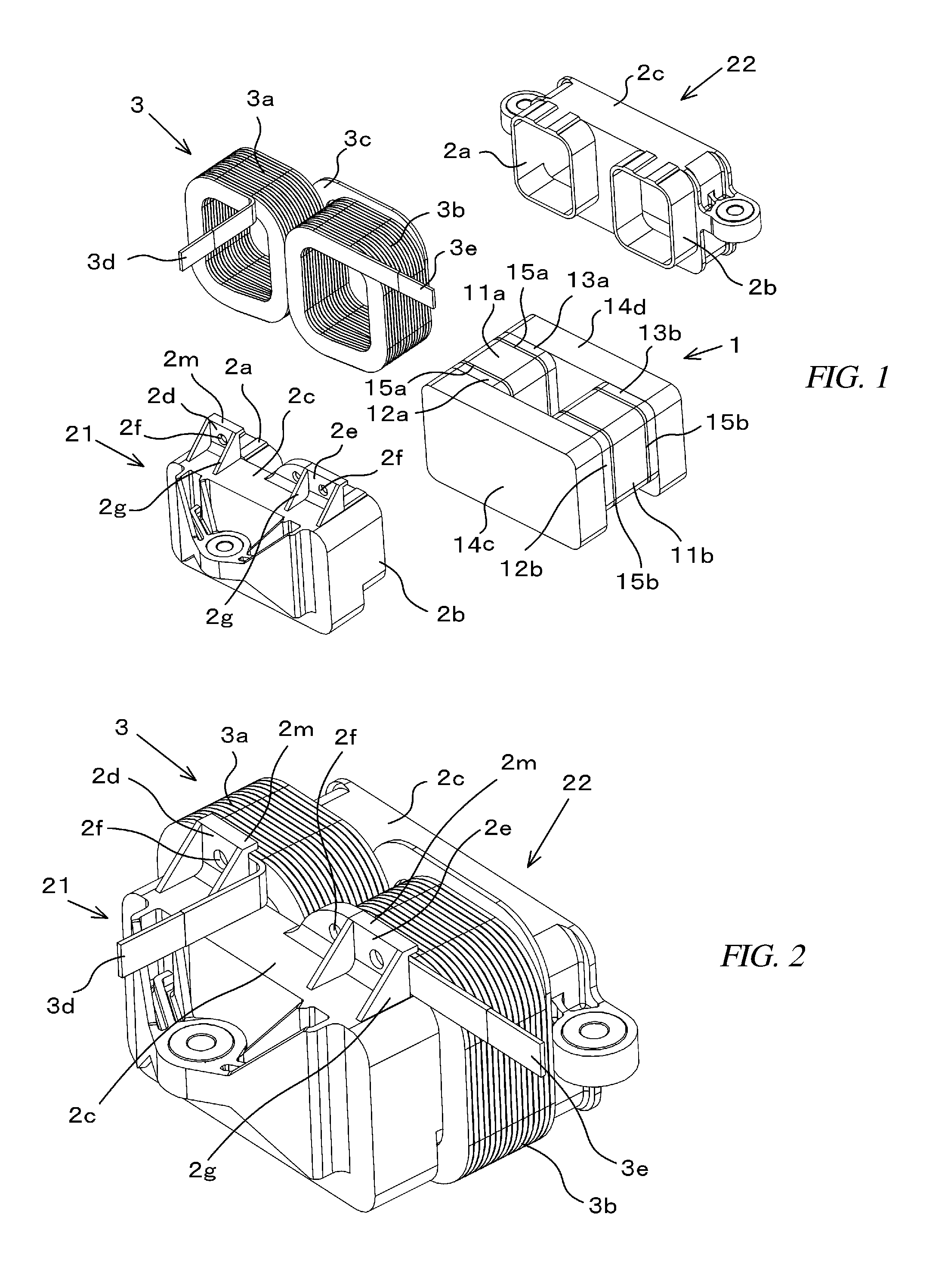
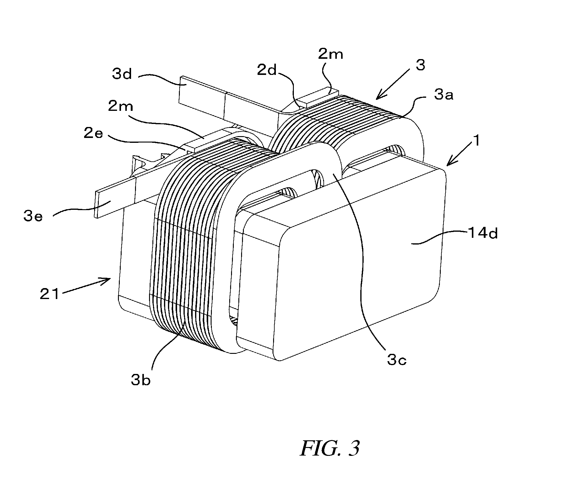
[0034]A reactor according to this embodiment includes an annular core 1, first and second resin covers 21, 22 covering the circumference of the core 1, and a coil 3 attached to the leg portions of the core 1. The annular core 1 is a powder magnetic core formed of pure iron, sendust, or Fe—Si alloy, a ferrite magnetic core, or a magnetic body like laminated steel sheets.
[0035]The annular core 1 includes two thick I-shaped cores 11a, 11b that form the right and left leg portions, four thin I-shaped cores 12a, 13a, 12b, 13b bonded with both sides of the respective thick cores 11a, 11b, and two block-shape cores 14c, 14d that form yokes. Those core pieces are bonded in a rectangular shape. According to this embodiment, spacers 15a, 15b that form respective magnetic gaps are fitted in bonding portions between the two thick I-shaped cores 11a, 11b and the four thin I-shaped cores 12a, 13a, 12b, 13b bonded with both ends of the respective thick cores 1...
second embodiment
2. Second Embodiment
[0065]According to this embodiment, as illustrated in FIG. 5, the wall portions 2d, 2e provided on the resin cover 21 are extended in accordance with the positions of the drawn portions 3d, 3e of the conductive wire as well as the final turn portion of the conductive wire forming the coil 3. This enables a bonding of not only the final turn portion of the conductive wire but also the protruding drawn portions 3d, 3e of the coil 3 with the wall portions 2d, 2e, and thus a further firm fixation of the conductive wire is accomplishable. Consequently, even the connection portions between the drawn portions 3d, 3e and the terminals are apart from each other, vibrations of the drawn portion are efficiently suppressed.
[0066]As explained above, according to this embodiment, the positions of the wall portions 2d, 2e and the shapes thereof are modifiable in accordance with the directions of the drawn portions 3d, 3e and the position of the connection portion with the termi...
third embodiment
3. Third Embodiment
[0067]According to this embodiment, as illustrated in FIG. 6, as the bonding portions, in addition to the upper wall portions 2d, 2e on the upper surface of the first resin cover 21, wall portions 2h that support the drawn portions 3d, 3e of the conductive wire, respectively, are provided at the side faces of the reactor. That is, various positions of the drawn portions 3d, 3e of the conductive wire are expected in accordance with the position of the terminal to be connected to the external electric circuit, and the position of the wall portion 2h is modifiable as appropriate in accordance with the positions of the drawn portions 3d, 3e like this embodiment.
PUM
| Property | Measurement | Unit |
|---|---|---|
| melting temperature | aaaaa | aaaaa |
| conductive | aaaaa | aaaaa |
| outer circumference | aaaaa | aaaaa |
Abstract
Description
Claims
Application Information
 - R&D
- Intellectual Property
- Life Sciences
- Materials
- Tech Scout
- Unparalleled Data Quality
- Higher Quality Content
- 60% Fewer Hallucinations
Browse by: Latest US Patents, China's latest patents, Technical Efficacy Thesaurus, Application Domain, Technology Topic, Popular Technical Reports.
© 2025 PatSnap. All rights reserved.Legal|Privacy policy|Modern Slavery Act Transparency Statement|Sitemap|About US| Contact US: help@patsnap.com


