
Needle cap remover and drug delivery device

a technology of needle cap and drug delivery device, which is applied in the direction of intravenous devices, infusion needles, infusion devices, etc., can solve the problems of undesirable exposure of needles, and achieve the effect of improving the removal of needle caps

Active Publication Date: 2016-12-08
SANOFI AVENTIS DEUT GMBH
View PDF4 Cites 4 Cited by
  • Summary
  • Abstract
  • Description
  • Claims
  • Application Information

AI Technical Summary

Benefits of technology

The present invention is about a needle cap remover for a drug delivery device that can safely and easily assemble the device without damaging the needle. The fabric tube, made of textile, rubber, or silicon, is a quick and easy way to assemble the needle cap remover without using adhesive. The fabric tube and the needle cap or rigid needle shield can be connected when the needle shield is assembled, and the fabric tube will contract or shrink when the needle cap is pulled off, allowing the needle cap to be safely removed from the drug delivery device. The invention is also about a drug delivery device comprising the needle cap remover. The needle cap remover prevents needle damage and contamination during assembly.

Problems solved by technology

This will usually result in an exposed needle which is undesirable in terms of needle safety or for person with a needle phobia.

Method used


Image

  • Needle cap remover and drug delivery device
  • Needle cap remover and drug delivery device
  • Needle cap remover and drug delivery device

Examples


first embodiment

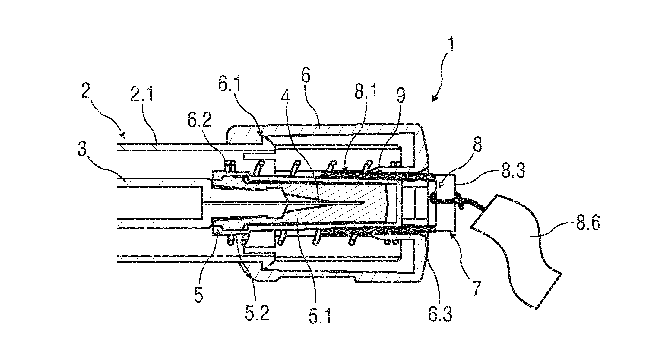
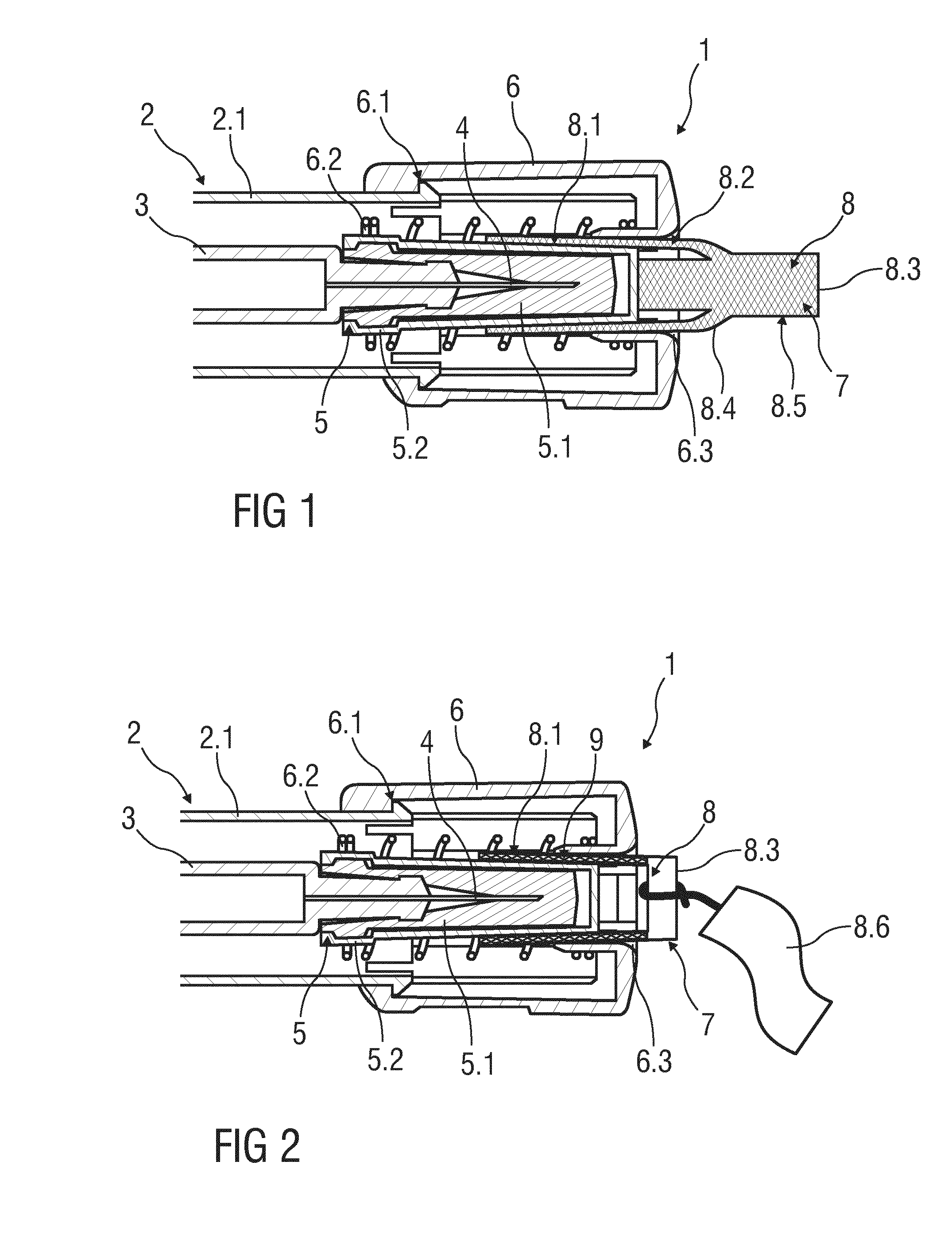
[0035] the needle cap remover 7 comprises a body 8 having a material which differs from the material of the needle cap 5.1 and / or the rigid needle shield 5 in at least one parameter. In particular, the needle cap 5.1 is made of a rubber and the rigid needle shield 5 is made of rigid polypropylene cap with the inner rubber needle cap 5.1 and the needle cap remover 7 is made of a thermoplastic material, e.g. fluoropolymer, polyolefine, PVC material or similar materials.

[0036]The needle cap remover 7 is inserted through an opening 6.3 of the needle shield 6 and arranged onto the needle shield 5. In an alternative embodiment (not shown), the needle 4 is only covered by the rubber needle cap 5.1 so that the needle cap remover 7 is arranged onto the rubber needle cap 5.1 directly.

[0037]The following description refers to a drug delivery device with a rubber needle cap covered by a rigid needle shield. This description applies also for a drug delivery device only with a rubber needle cap w...

third embodiment

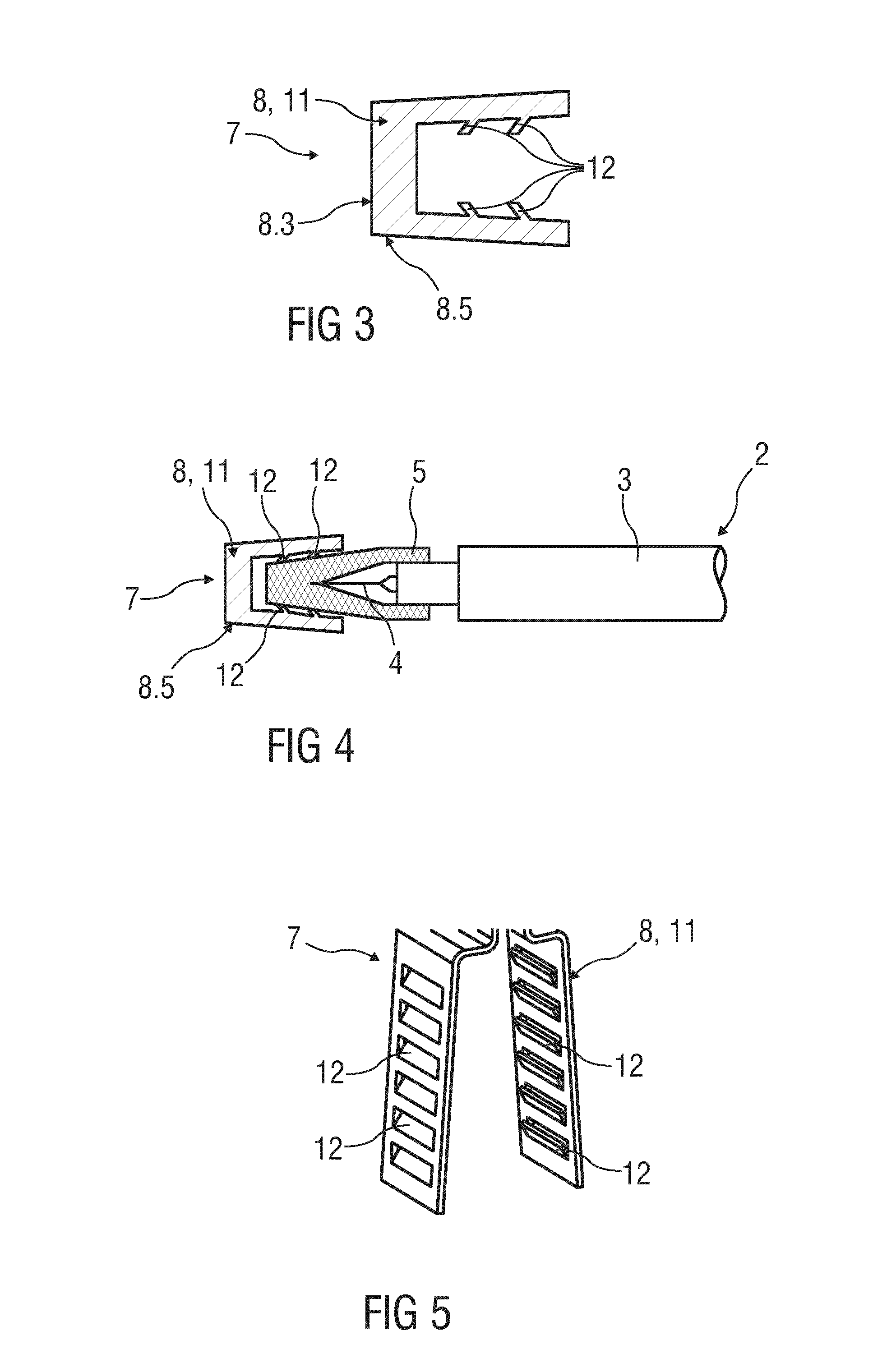
[0050]FIG. 3 shows a partial longitudinal section of a further improved needle cap remover 7. The body 8 is formed as a hollow sheet metal part 11 adapted to be arranged onto the rigid needle shield 5. The body 8 has a clamp shape or U-shape or the form of a sleeve or cylinder.

[0051]The body 8 is made of a thin sheet metal. Hence, the needle cap remover 7 and the rigid needle shield 5 differs at least in the material and / or the resistance, wherein the rigid needle shield 5 is made of a rigid polypropylene material and the needle cap remover 7 is made of a thin metal sheet profile.

[0052]Furthermore, the body 8 comprises protrusions 12 which extend from the inside wall into the inner hole. Preferably, the body 8 comprises a plurality of inwardly directed protrusions 12 which are formed as hooks. The hooks may take a number of different forms. Preferably, the hooks are slightly angled and inwardly protrude into the direction of the pull-off-movement of the needle cap remover 7.

[0053]FI...


PUM


Abstract

The invention refers to a needle cap remover (7) for a needle cap (5.1) of a drug delivery device (2). The needle cap remover (7) comprises a body (8) having a material which differs from the material of the needle cap (5.1) or of a rigid needle shield (5) encasing the needle cap (5.1) in at least one parameter, wherein a body portion (8.1), which covers the needle cap (5.1) or the rigid needle shield (5) encasing the needle cap (5.1), is adapted to capture the needle cap (5.1) or the rigid needle shield (5) encasing the needle cap (5.1) by a positive and / or non-positive connections before or during removing of the needle cap (5.1) and is adapted to shrunk when a pulling force is applied.

Description

TECHNICAL FIELD[0001]The invention relates to a needle cap remover for removing a needle cap from a needle of a drug delivery device, and to such a drug delivery device.BACKGROUND OF THE INVENTION[0002]Many drug delivery devices of the prior art, such as auto-injectors, syringes, have been developed for self-administration of the drug.[0003]To protect the needle of the drug delivery device from damage or to protect people from needle-prick injuries before using of the device, the needle of the drug delivery device is covered by a protective needle cap of a flexible material which can be encased by a rigid, in particular a plastic needle shield, the so-called rigid needle shield (shortly named RNS).[0004]In order to prepare the drug delivery device for delivering a dose the protective needle cap has to be removed from the needle. This may be done by gripping the protective needle cap and pulling it away from the needle. This will usually result in an exposed needle which is undesirab...

Claims


Application Information

Patent Timeline
IPC IPC(8): A61M5/32
CPCA61M5/3257A61M5/3204A61M5/326A61M2005/3267
Inventor KEIM, MORITZHUTHMACHER, WINFRIEDNOBER, PETER
Owner SANOFI AVENTIS DEUT GMBH
Learn More