
Drop In Trigger Assembly

a technology of modularity and trigger assembly, which is applied in the direction of firing/trigger mechanisms, weapons, weapon components, etc., can solve the problems of inconsistent trigger let-off and creep of triggers, and achieve the reduction of the pull weight of triggers, the effect of reducing the pull effort rate and improving the utilization rate of ammunition

Active Publication Date: 2016-12-15
ART IDEAS LLC
View PDF12 Cites 23 Cited by
  • Summary
  • Abstract
  • Description
  • Claims
  • Application Information

AI Technical Summary

Benefits of technology

The invention is a drop-in modular trigger for an AR-15 semi-automatic rifle. It aims to increase the firing rate, lower the trigger pull effort, enable better utilization of ammunition, improve accuracy, and replace the trigger in less than an hour without the need for a gunsmith. These technical effects are achieved through a more efficient trigger assembly and a reduced pull weight of the trigger, resulting in a more pleasant shooting experience and improved performance of the rifle.

Problems solved by technology

It is known that stock triggers in AR-15 style rifles have triggers with accuracy-robbing characteristics, such as, but not limited to, excessive trigger take-up and a propensity to accumulate grit in the trigger mechanism causing trigger creep that makes for inconsistent trigger let-off.

Method used


Image

  • Drop In Trigger Assembly
  • Drop In Trigger Assembly
  • Drop In Trigger Assembly

Examples


Embodiment Construction

[0043]In the following description, and for the purposes of explanation, numerous specific details are set forth in order to provide a thorough understanding of the various aspects of the invention. It will be understood, however, by those skilled in the relevant arts, that the present invention may be practiced without these specific details. In other instances, known structures and devices are shown or discussed more generally in order to avoid obscuring the invention. In many cases, a description of the operation is sufficient to enable one to implement the various forms of the invention, particularly when the operation is to be implemented in software. It should be noted that there are many different and alternative configurations, devices and technologies to which the disclosed inventions may be applied. The full scope of the invention is not limited to the examples that are described below.

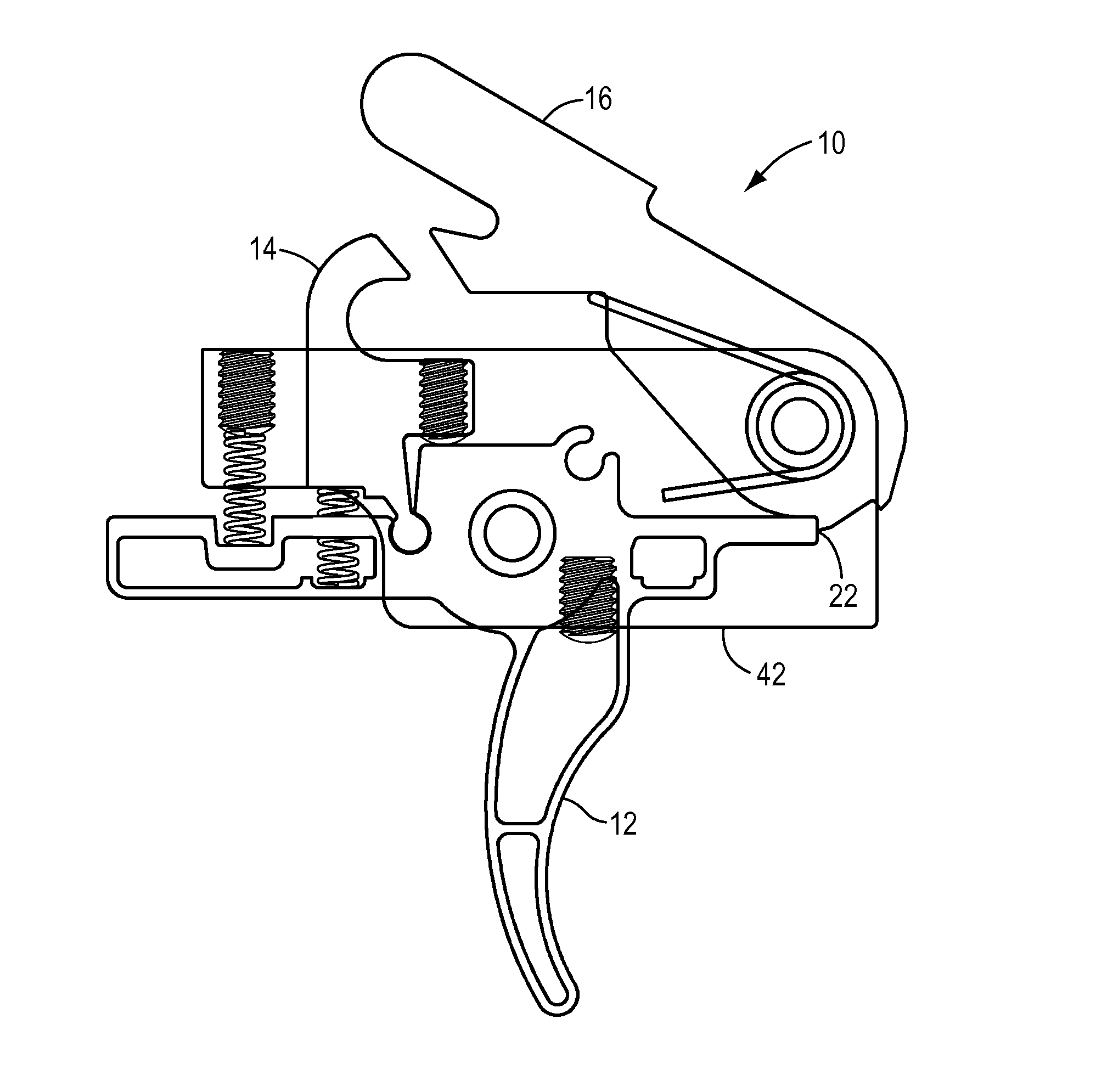
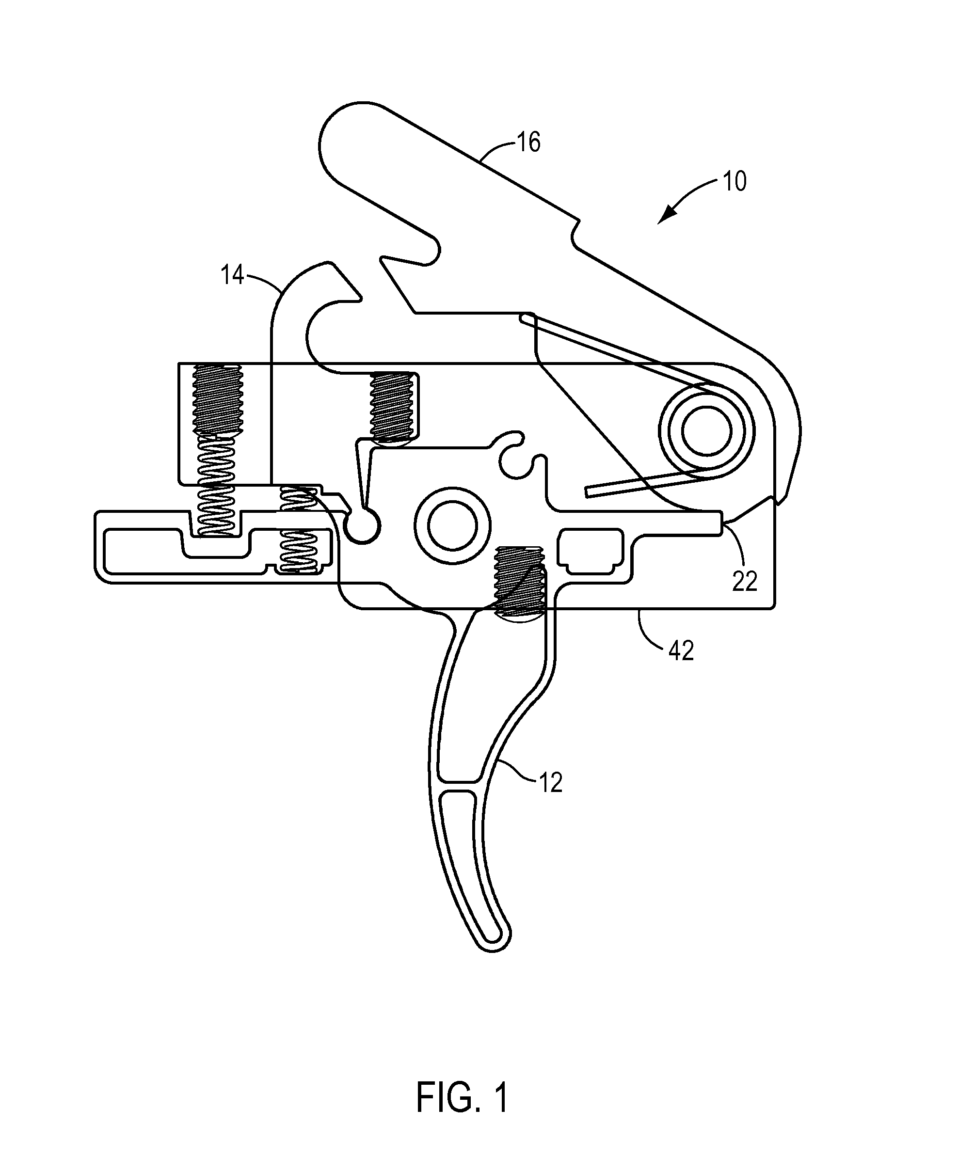
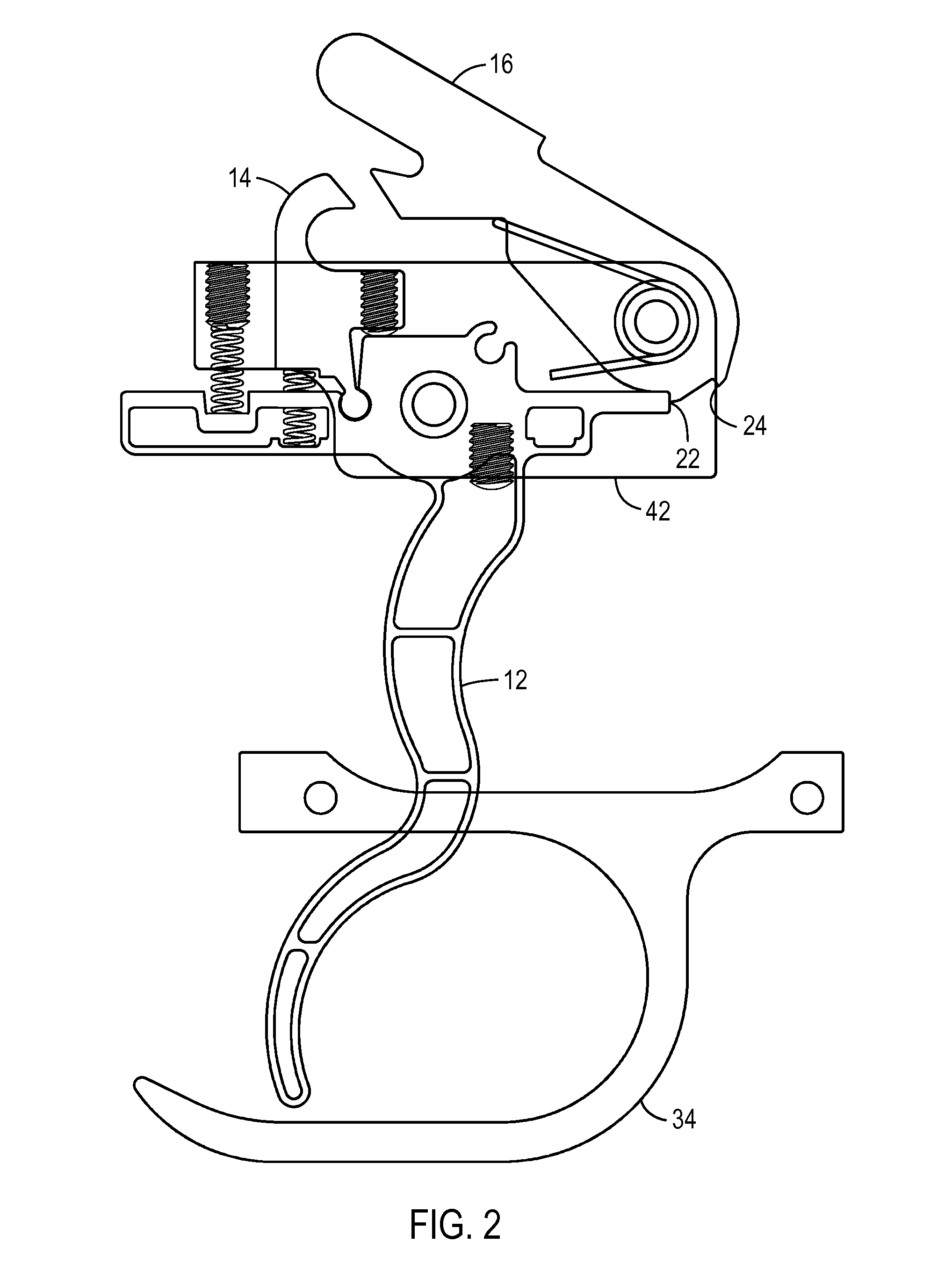
[0044]It should also be pointed out that the front of the trigger assembly is the direct...


PUM


Abstract

A modular trigger and hammer assembly having a hammer, a trigger, a disconnector and a hammer spring for use in a weapon including at least a lob including a firing notch, a safety notch; and a curved landing flat. Also including a trigger needle bearing and a hammer needle bearing.

Description

CROSS REFERENCE TO RELATED APPLICATION[0001]This application claims the benefit of provisional Application 61 / 880,947, filed Sep. 22, 2013 bearing the same title as this application. This earlier filed application is hereby incorporated by reference in its entirety.BACKGROUND OF THE INVENTION[0002]Field of the Invention[0003]This invention is a drop-in modular trigger assembly for use in replacing the stock trigger assembly of a semi-automatic rifle such as the “Colt” brand, “AR-15” brand (“Colt” and “AR-15” are trademarks of Colt Industries) as well as similar semi-automatic rifles or clones of the “Colt”“AR-15” semi-automatic rifle made by many companies throughout the world. The device is a replacement of the stock or original equipment trigger assembly carried in the lower receiver portion of a semi-automatic rifle. This drop-in modular trigger assembly is made to replace the original trigger provided with the stock rifle without impairing the functionality of the original rifle...

Claims


Application Information

Patent Timeline
IPC IPC(8): F41A19/15F41A19/14F41A19/10F41A19/16
CPCF41A19/15F41A19/10F41A19/14F41A19/16
Inventor ELFTMANN, ARTHUR J.
Owner ART IDEAS LLC
Learn More