

Safety-switch device for use on a movable device
Patent Information
- Authority / Receiving Office
- US · United States
- Current Assignee / Owner
- HAAKE ANDRE
- Publication Date
- 2016-12-15
Smart Images
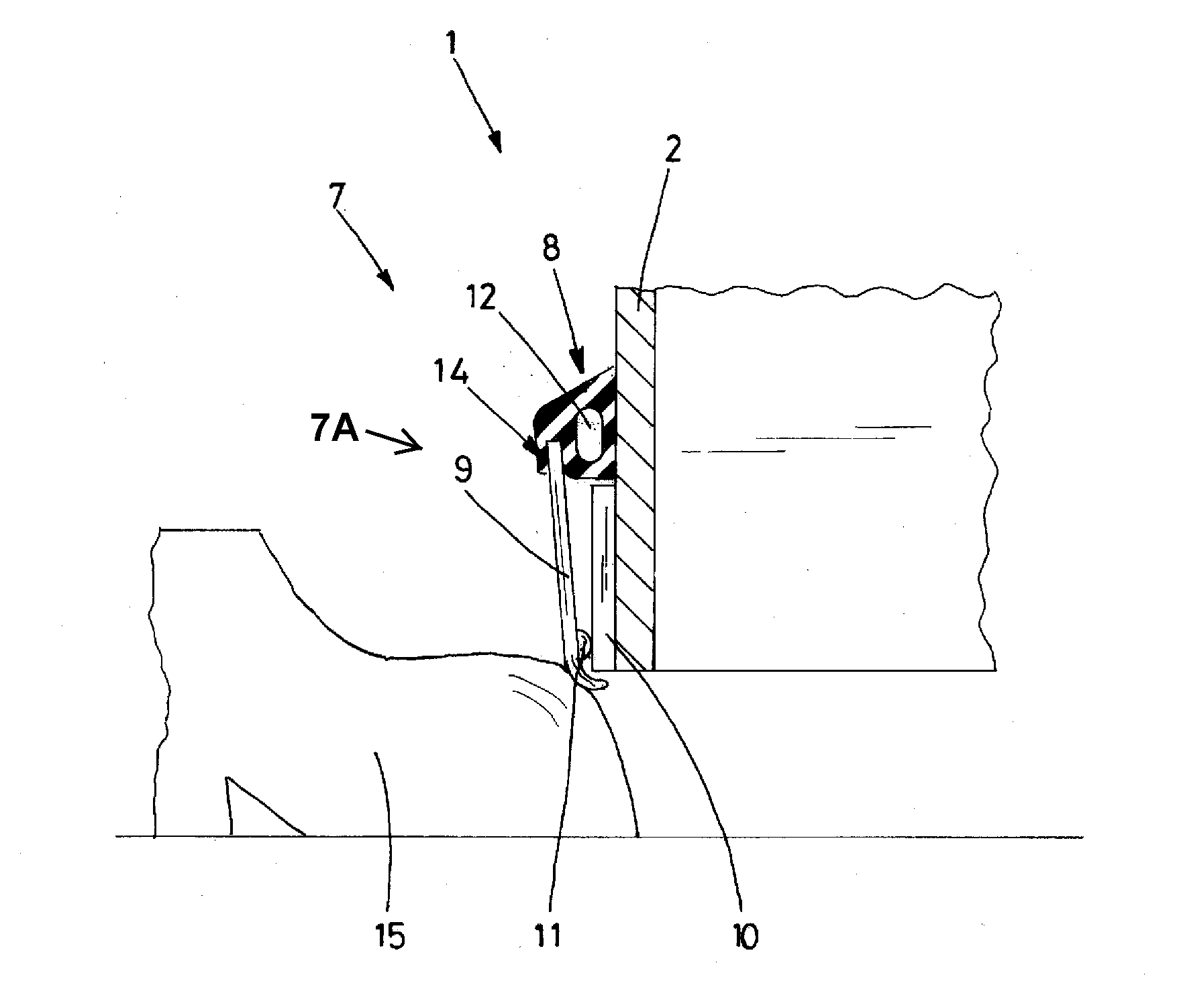
Figure 1 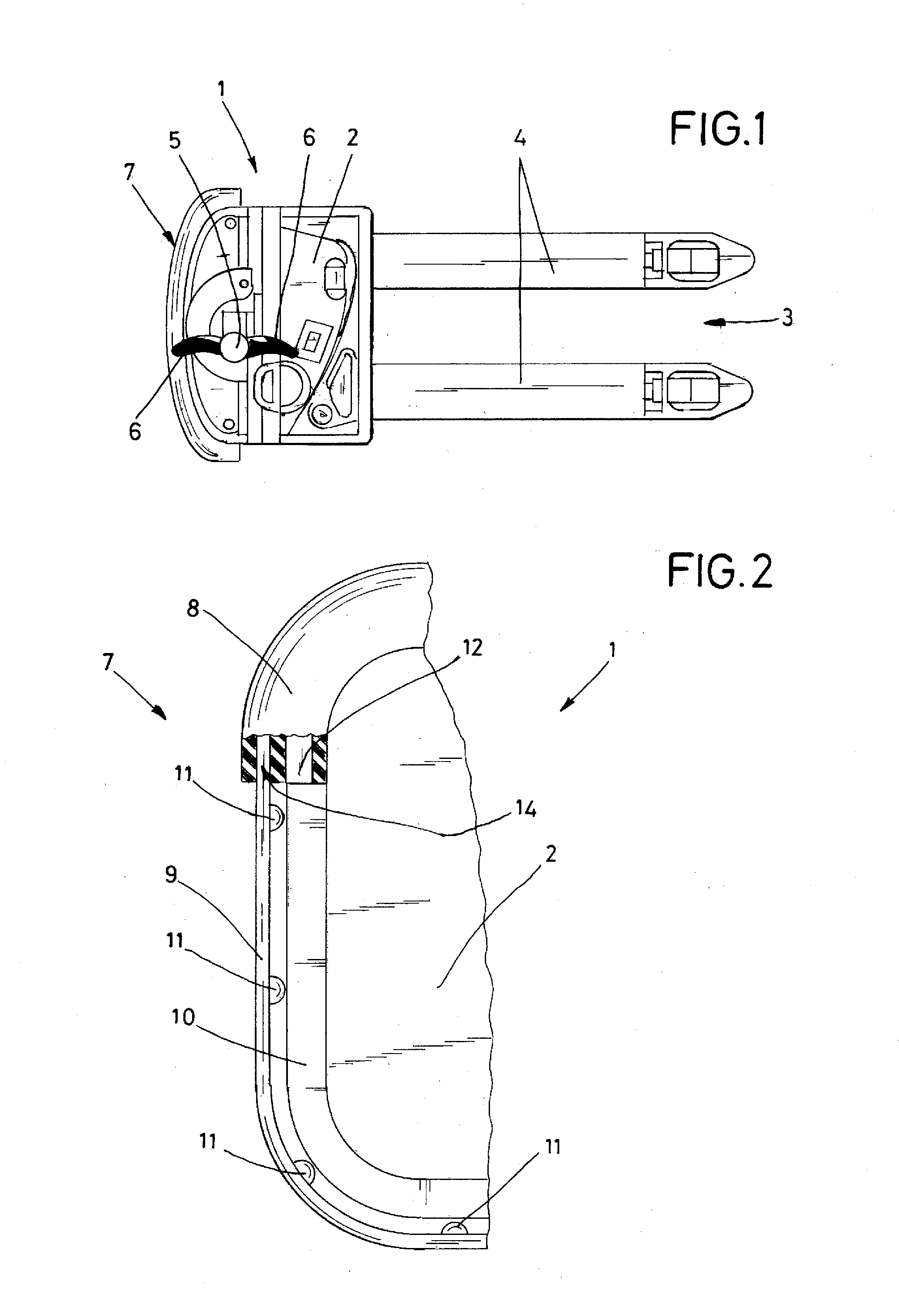
Figure 2 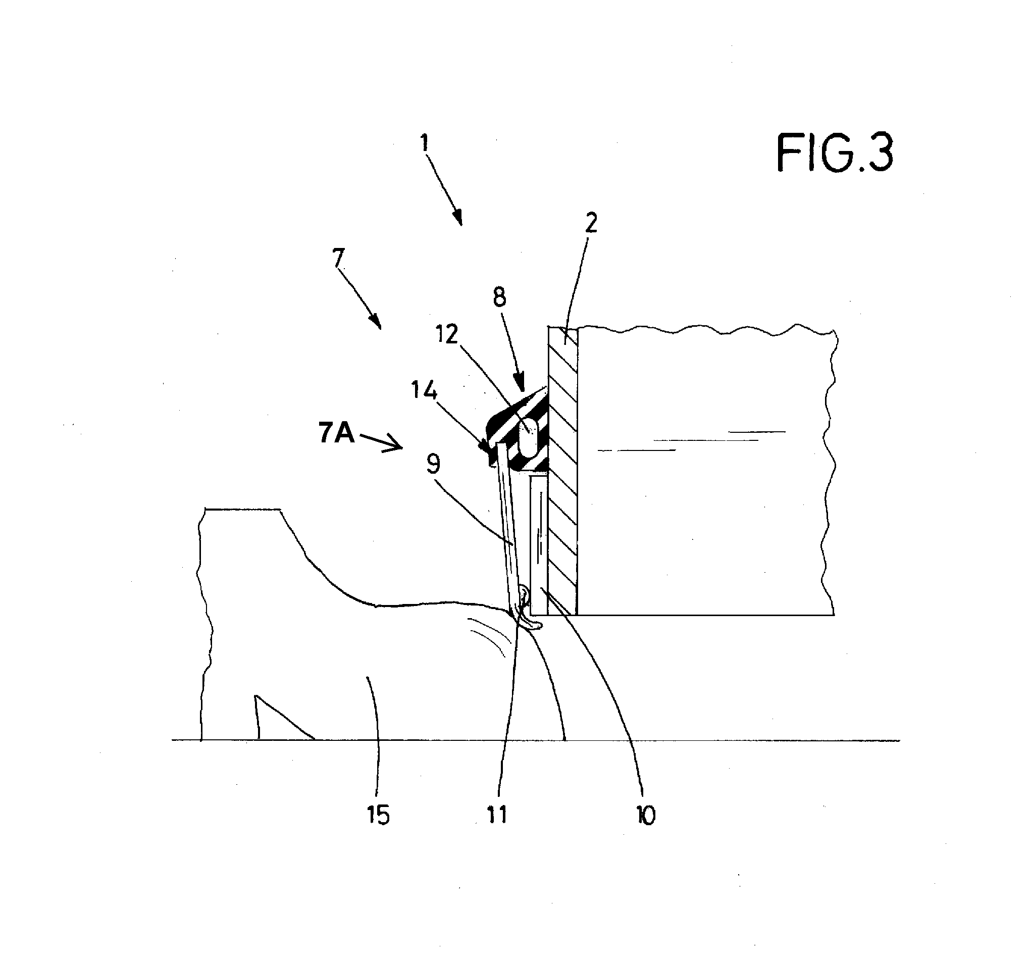
Figure 3
Abstract
Description
[0001] Field of the Invention
[0002] The invention relates to a safety-switch device for use on movable devices.
[0003] Discussion of Prior Art
[0004] It is known in the industry to provide a conventional safety-switch device on movable devices as a means of accident prevention. Such movable devices can, for example, be parts of larger apparatus and examples of such movable devices include freely movable articulated arms, booms, etc. The movable devices may, however, also include vehicles, such as a forklift truck. Hereinafter, reference is made to an electric motor powered forklift truck as the movable device, but it is understood that this reference is only by way of example and that it includes other types of movable devices.
[0005] It is known to provide a forklift truck with a conventional safety-switch device, whereby the switch is a switch, i.e., a flexible, deformable, strip or tube-like element, that is placed on the housing of the forklift truck. The purpose o...