Thermal energy storage member and storage container using the same, and refrigerator using the same

a technology of storage containers and energy storage components, which is applied in the direction of domestic refrigerators, lighting and heating apparatus, and domestic cooling apparatus, etc., can solve the problems of unfavorable uniform cooling inside the cabinet, and achieve the effect of sufficient dissipation capabilities

Active Publication Date: 2016-12-22
SHARP KK
View PDF9 Cites 14 Cited by
  • Summary
  • Abstract
  • Description
  • Claims
  • Application Information

AI Technical Summary

Benefits of technology

[0056]According to the present invention, suffi

Problems solved by technology

In this configuration, and particularly in the case of direct-cooling refrigeration containers, the flow of cold air (dissipatio

Method used


Image

  • Thermal energy storage member and storage container using the same, and refrigerator using the same
  • Thermal energy storage member and storage container using the same, and refrigerator using the same
  • Thermal energy storage member and storage container using the same, and refrigerator using the same

Examples


first embodiment

[0083]A thermal energy storage member and a storage container using the same, and a refrigerator using the same, according to a first embodiment of the present invention, will be described with reference to FIG. 1 through FIG. 14. Note that in all of the drawings described below, dimensions, ratios, and so forth, of the components, have been changed as appropriate to facilitate understanding.

example 1-1

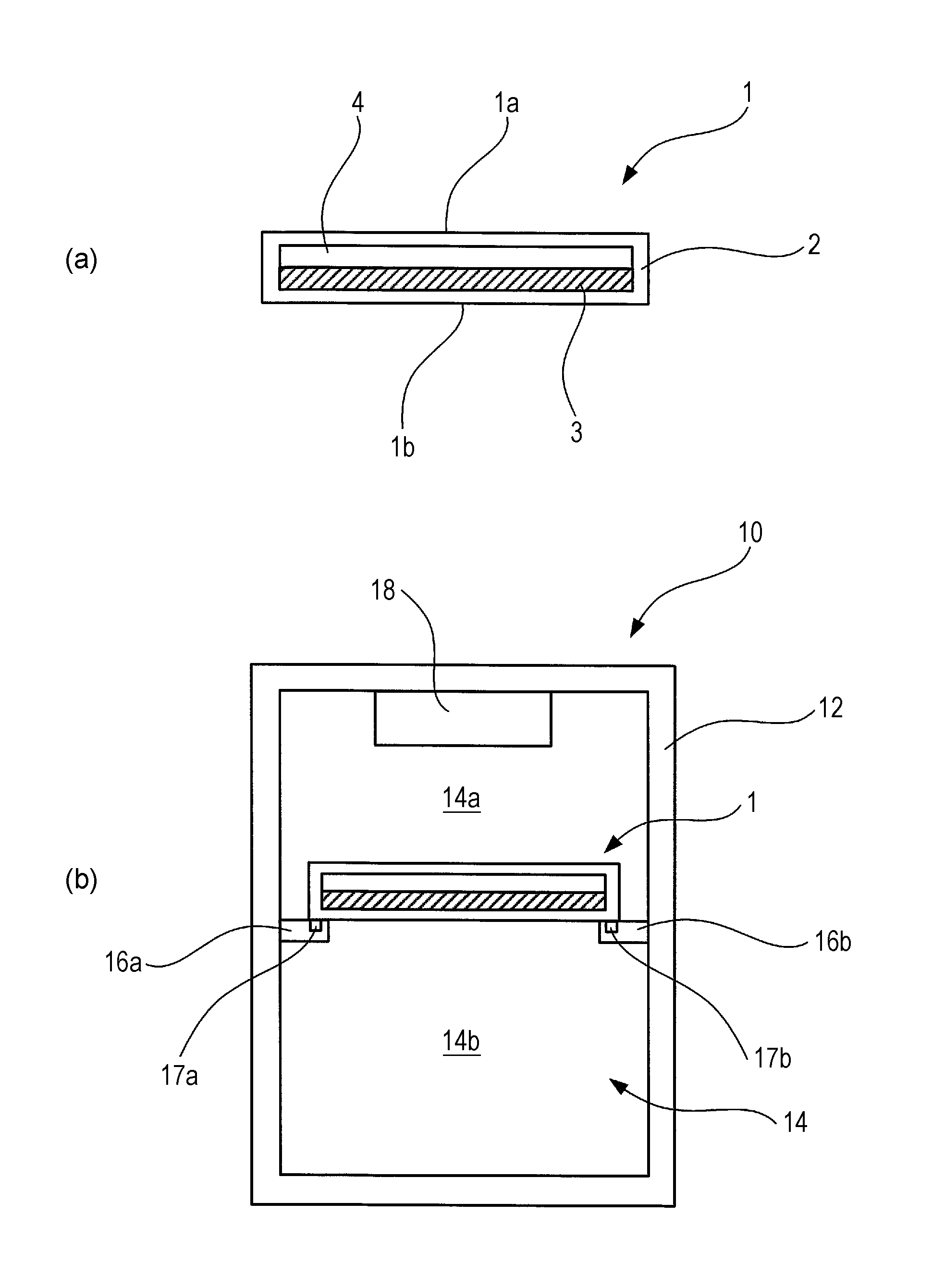
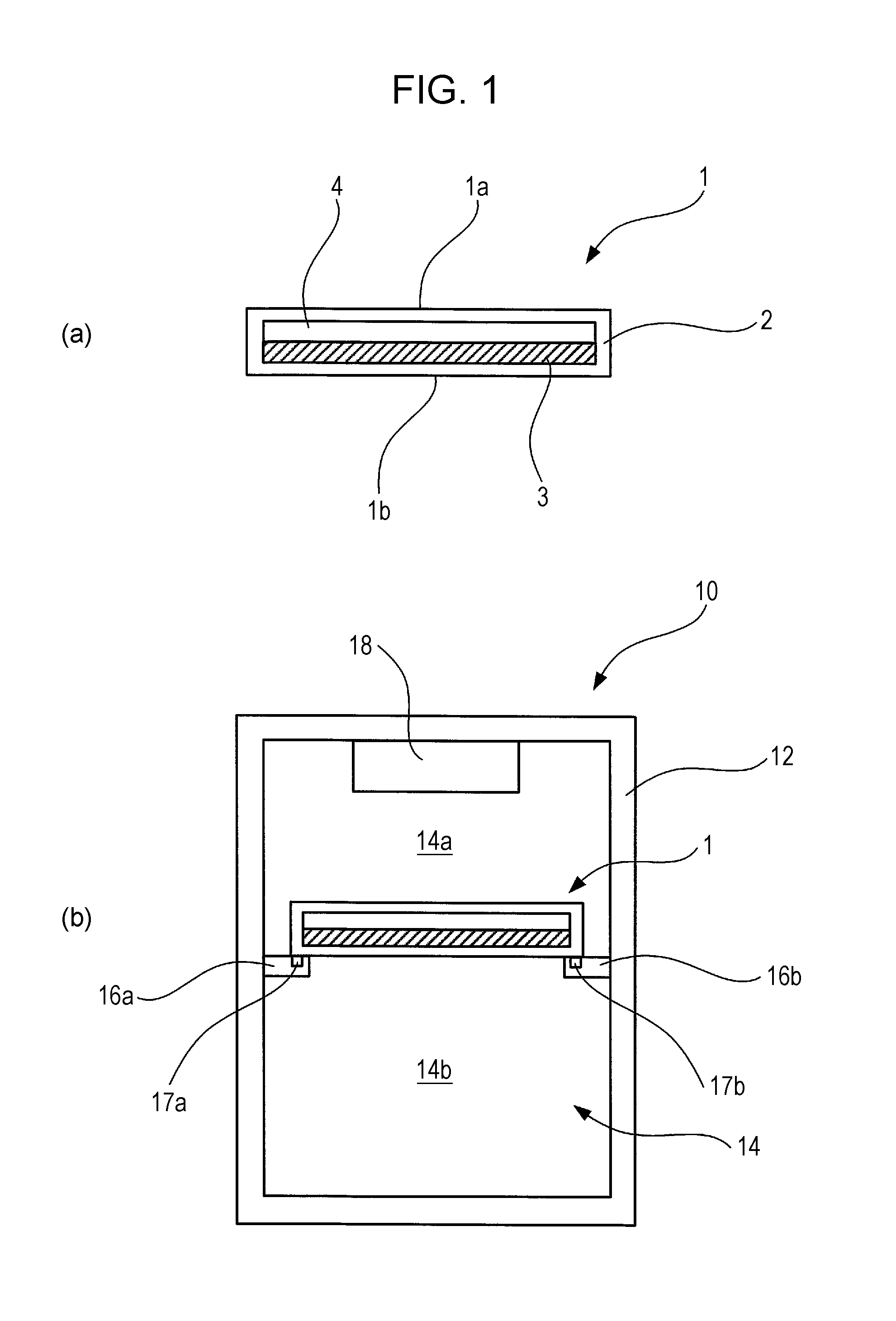
[0084]FIG. 1 illustrates a schematic configuration of a thermal energy storage member and a storage container using the same, and a refrigerator using the same, according to Example 1-1 of the present embodiment. A thermal energy storage member 1 is shaped as a cuboid in the form of a thin plate, having an opposed upper face 1a and lower face 1b. FIG. 1(a) illustrates a cross-section of the thermal energy storage member 1, taken along the normal line direction of the surface of the thin plate shape. The thermal energy storage member 1 includes a hollow package material 2 that makes up the outer shape of the cuboid having the form of a thin plate, a thermal energy storage material 3 filled in the hollow space within the package material 2, and a gaseous layer (e.g., an air layer) 4 filled in the hollow space within the package material 2.

[0085]A thermal energy storage material of latent heat that exhibits reversible phase change between liquid phase and solid phase at a predetermined...

example 1-2

[0113]An Example 1-2 of the thermal energy storage member and storage container using the same, and refrigerator using the same, according to the present embodiment, will be described with reference to FIGS. 3 through 10. FIG. 3 illustrates the structure of a refrigerator 120 used in the present example. FIG. 3 illustrates a state of inside the cabinet of the refrigerator 120 as viewed from the opening / closing door, in which illustration of the opening / closing door is omitted. The refrigerator 120 is provided with, in order from top to bottom within an outer case 121, a freezing chamber 122, a cooling chamber 123, and a refrigeration chamber 124. Below the refrigeration chamber 124 is provided a mechanical chamber 129 where a part of the cooling mechanism, such as the compressor and the like, is stored. A cooler 126 is provided on the inner wall portion at the back side between the freezing chamber 122 and cooling chamber 123. The refrigeration chamber 124 is provided with shelves 1...


PUM


Abstract

It is an object of the present invention to provide a thermal energy storage member having sufficient dissipation capabilities and a storage container using the same, and a refrigerator using the same.
A thermal energy storage member 1 includes: a thin-plate outer shape having an opposing upper face 1a and lower face 1b; a thermal energy storage material 3 filled in the inside of a package material 2; and a thermal conduction amount adjusting portion 4 that, in a case where difference occurs between temperature at the upper face 1a side and temperature at the lower face 1b side, reduces difference in thermal conduction amount per unit of time at the upper face 1a and the lower face 1b.

Description

TECHNICAL FIELD[0001]The present invention relates to a thermal energy storage member used for temperature preservation and a storage container using the same, and to a refrigerator using the same.BACKGROUND ART[0002]There are known storage containers that store goods at temperatures different from the ambient temperature, such as refrigerators and heating cabinets. The temperature within the cabinet of such storage containers becomes closer to the ambient temperature due to external factors, such as opening / closing cabinet doors, electric power outage, and so forth. To prevent this from occurring, there has been proposed a storage container in which a thermal energy storage member is disposed at an optional location within the cabinet, and the thermal energy storage member is frozen under normal operations, whereby the storage container can be maintained at an intended temperature by using the latent heat of fusion of the thermal energy storage member even if such external factors ...

Claims


Application Information

Patent Timeline
IPC IPC(8): F25D11/00C09K5/06F25D23/06
CPCF25D11/006F25D2303/084C09K5/063F25D23/069F25D11/00F25D2303/082F25D2303/08222F25D2303/08223
Inventor BESSHO, HISANORIKASE, TOMOKOYAMASHITA, TAKASHIUTSUMI, YUKAMIYATANI, TOMOHISAIDE, TETSUYASAWADA, DAIJI
Owner SHARP KK
Why Eureka
Try Eureka