Barrier assembly

a barrier and assembly technology, applied in the field of barriers, can solve the problems of escaping toxic gases, a significant risk to the life and health of third parties in the vicinity of residential areas, and a significant risk to personnel working around oil fields or operating/refining plants, and achieve the effect of increasing the surface area

Pending Publication Date: 2022-05-19
ENI SPA
View PDF2 Cites 0 Cited by
  • Summary
  • Abstract
  • Description
  • Claims
  • Application Information

AI Technical Summary

Benefits of technology

[0010]A great advantage of using gas-permeable wall members to mitigate gas leaks is that the gas-permeability maintains natural ventilation so surprisingly reducing the formation of a potentially explosive atmosphere where the leaking gas meets the barrier assembly, e.g. at the gas leak side, for example where the gas may be flammable. A gas permeable barrier assembly with e.g. openings or perforations to admit gas is also surprisingly effective at controlling e.g. reducing lateral spread of the leaked gas in particular.
[0038]Optionally the barrier assembly is partially filled with a matrix comprising a material that reacts with the target gas. For example, the barrier assembly may be filled to a certain height / vertical level. This can be advantageous in providing sufficient dissipation of the gas and rapid reduction in concentration of the gas, while reducing material costs in comparison with fully filled barrier assemblies. This arrangement is particularly suitable for locations where gas is being transported at a low level such as through pipelines, for example.

Problems solved by technology

Just as an explosive release, or an ignition reaction, is a serious safety concern during hydrocarbon production, the escape of toxic gases is also a significant risk to personnel working around an oil field or operating / refining plants.
Due to the potential for toxic gases to be carried on the wind, there is a further risk to life and health of third parties in nearby residential areas, where the gases may reach before their concentration has fallen to a non-hazardous level.

Method used


Image

  • Barrier assembly
  • Barrier assembly
  • Barrier assembly

Examples


example 1

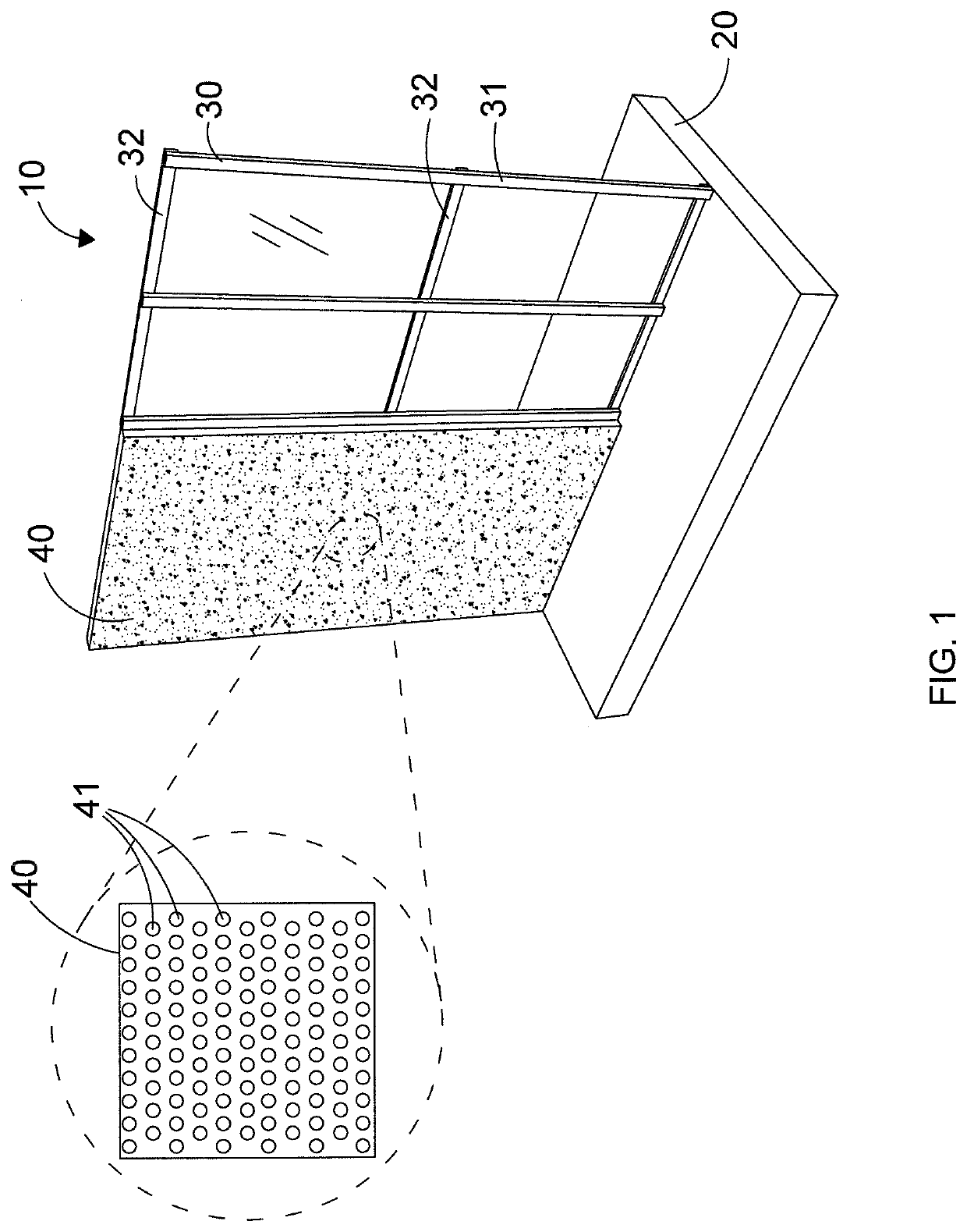
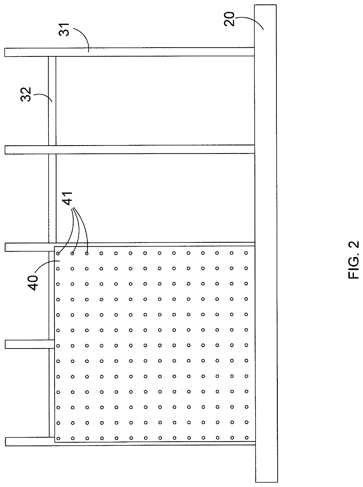
[0072]The apparatus of FIGS. 1-5 was used in a test as follows: A source of H2S gas was allowed to escape from a gas source upstream of the barrier assembly of FIGS. 1-5. A hypothetical target located 200 m downstream of the gas source and on the other (downstream) side of the barrier assembly comprised a sensor capable of detecting the gas concentration at a height of 1.7 m. The sensor measured the gas concentration at the downstream location. The criterion for the test was that at least the concentration threshold of H2S of 600 ppm should be reached within 75 seconds of initiation of gas release. The 75 s time limit corresponds to an estimated time required to put on a mask. The barrier assembly, 5 m high and 20 m wide, comprised a perforated vertical wall having an empty space fraction of 25% obtained with ¼″ holes spaced at approximately W. The target located 200 m from the release source was affected by a concentration of approximately 200 ppm after 75 s. It is confirmed the ef...

example 3 (

Passive Wall)

[0088]It is considered a vertical perforated barrier located at 15 m from the release of gas. Void fraction is 25% and holes size ¼″. The dimensions of the wall (i.e. barrier) are the same as the barrier of example 1.

[0089]It is considered the horizontal release of gas, the release size is 50 mm (hole size) and the position of the hole is @ 1 m above ground.

[0090]A gas flow (release pressure 150 barg, temperature 80° C.) with the following composition: methane as main component (97% mol) and H2S concentration at 3% mol / mol is directed toward the wall.

[0091]On the other side of the wall (outlet) the gas stream is calculated, by means of fluidodinamics simulations (using the same method as described in example 2), at 5 meters before the barrier, 150 meters after the barrier and 200 meters after the barrier.

5 meters 150 meters 200 meters beforeafterafterthe barrierthe barrierthe barrierppm H2SPerforated barrier 47459867(Void fraction 25%. Holes size ¼″)

example 5 (

Reactive Wall)

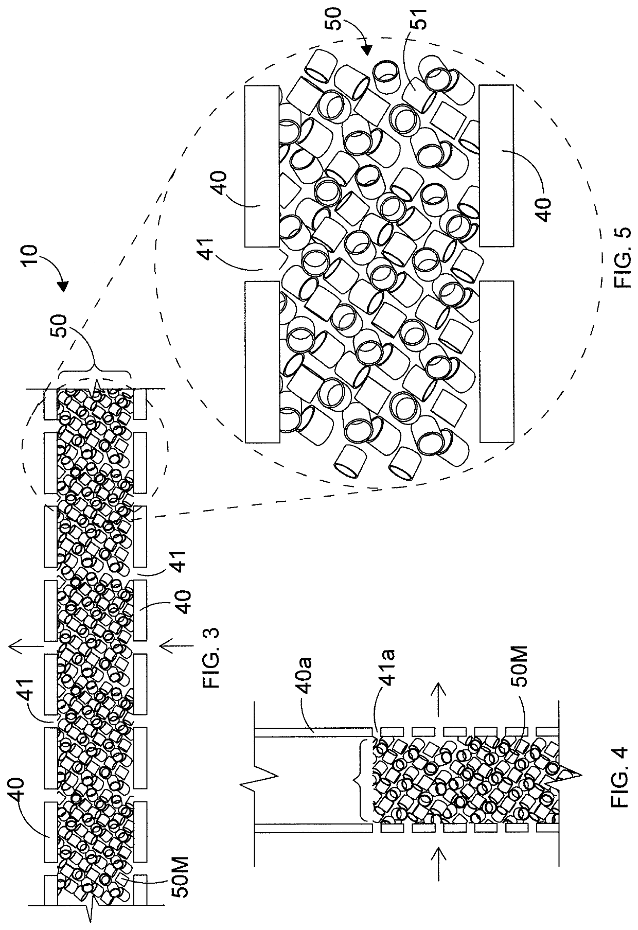
[0098]It is considered a porous barrier, filled with commercial scavenger R7J (i.e. a H2S scavenger) produced by Sulfatrap®, whose composition is reported below in table 1, whose diameter is 70-100 mesh, the thickness of the scavenger filling is 16 cm.

[0099]A gas flow (gas flow rate: 0.25 m s−1, temperature: 25° C.) with the following composition: 14,99% H2S and 85.01% N2, is directed toward the wall.

[0100]On the other side of the wall (outlet) the gas stream is detected after 1 minute and analyzed with a gas chromatograph.

[0101]The gas flow composition on the other side of the wall (outlet composition) shows a sharp decrease of H2S (H2S content: 33 ppm, N2: one hundred complement).

[0102]Therefore, there is a sharp reduction of the toxicity for a person present on the other side (outlet) of the wall.

TABLE 2Chemical composition of the commerical sorbents and their Sulphur Absorbent CapacityActivatedAluminiumAluminioCopper IICopperIron IIICharcoalOxideSilicateHydroxideOx...


PUM


Abstract

A barrier assembly used in the protection of personnel at worksites and / or residential areas from escapes of gas. Such a barrier assembly controls the lateral and vertical spread of gas in the event of an escape of the gas, even more particularly toxic gas. The barrier assembly can be used at operating sites where gases are produced, and in particular where high concentrations of toxic gases (e.g. CO2, H2S, SO2, mercaptans etc.) are present. The barrier assembly can, optionally acting as a safety system in the event of an accidental uncontrolled release of these toxic gases into the atmosphere.

Description

CROSS-REFERENCE TO RELATED APPLICATIONS[0001]This application is a national stage application, filed under 35 U.S.C. § 371, of International Patent Application No. PCT / US PCT / IB2020 / 051197, filed on Feb. 13, 2020, that claims priority from Italian Patent Application No. 102019000002079 filed on Feb. 13, 2019, the entire disclosure of each of which is incorporated herein by reference.BACKGROUND OF THE DISCLOSURE1. Field of the Disclosure[0002]The present disclosure relates to a barrier assembly for use in protection of personnel at worksites and / or residential areas from escapes of gas. More particularly, this disclosure relates to a barrier assembly for controlling the lateral and vertical spread of gas in the event of an escape of said gas, even more particularly toxic gas. The disclosure finds application in all operating sites where gases are produced, and in particular where high concentrations of toxic gases (e.g. CO2, H2S, SO2, mercaptans etc) are present, optionally acting as...

Claims


Application Information

Patent Timeline
Patent Type & Authority Applications(United States)
IPC IPC(8): E21F7/00E04B2/74E04B1/94
CPCE21F7/00E04G21/243E04B1/946E04B2/7457E04B1/92B01D53/22B01D53/229B01J8/009
Inventor DECARLI, LUCALA ROSA, LAURADE ANGELIS, ALBERTO RENATOVIGNALI, ANDREA
Owner ENI SPA
Why Eureka
Try Eureka