

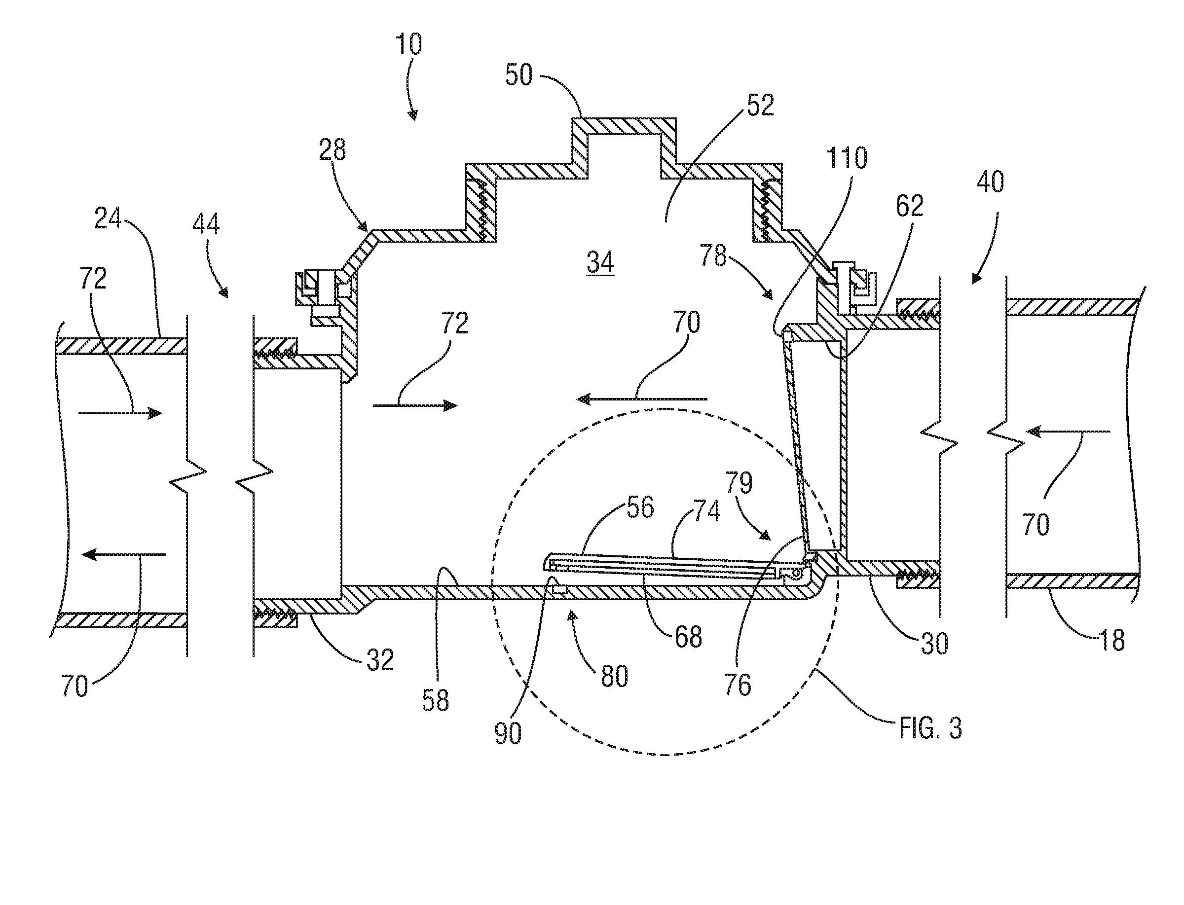
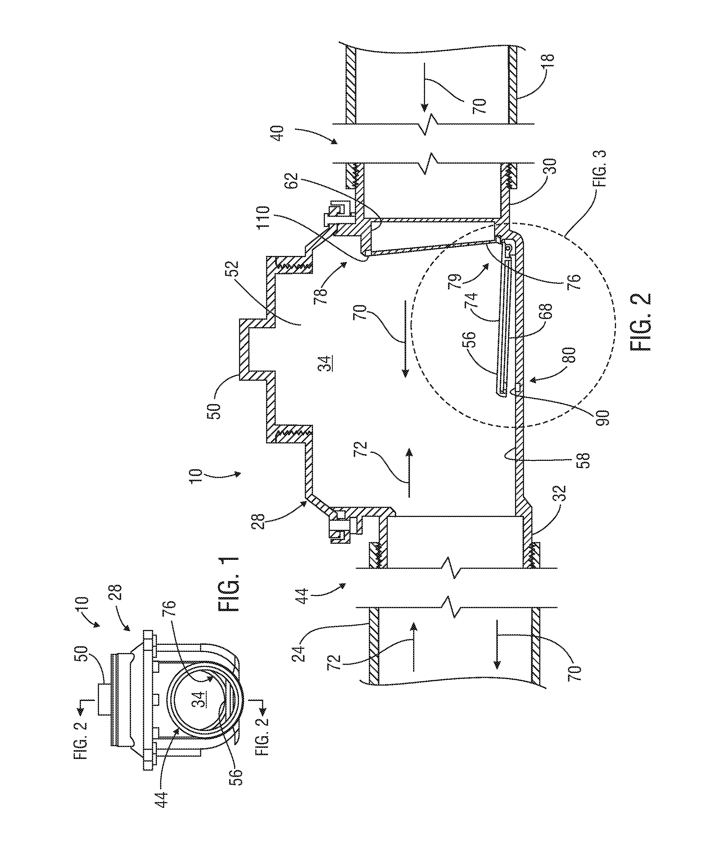
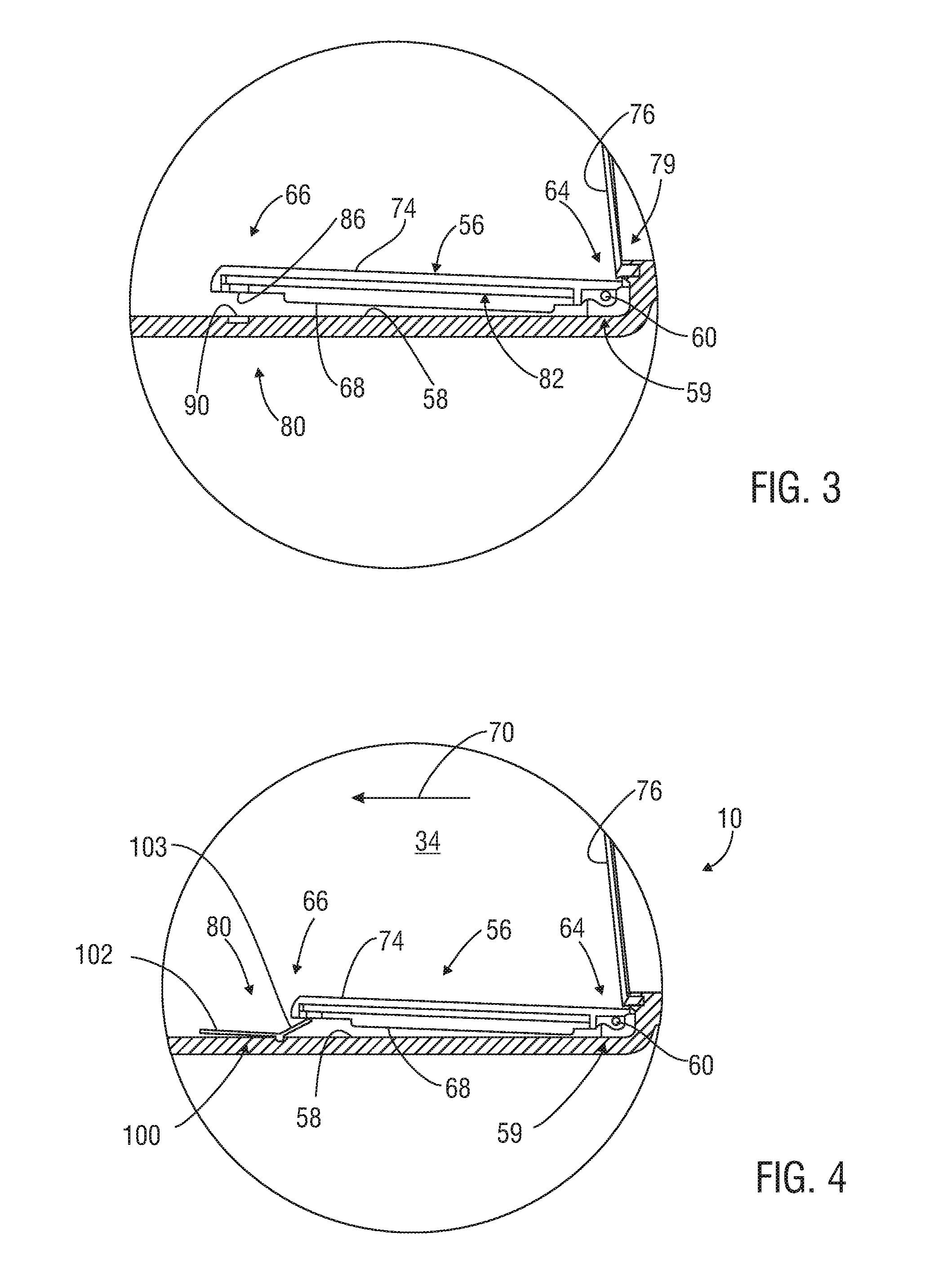
Normally-open backwater valve with suspended flapper
- Summary
- Abstract
- Description
- Claims
- Application Information
AI Technical Summary
Benefits of technology
Problems solved by technology
Method used
Image

Examples
Embodiment Construction
[0020]The present inventions now will be described more fully hereinafter with reference to the accompanying drawings, in which at least some preferred embodiments of the invention are shown. The inventions of this disclosure may, however, be embodied in many different forms and should not be construed as limited to the embodiments set forth herein; rather, these embodiments are provided so that this disclosure will be thorough and complete and fully convey the scope of the inventions provided herein to those skilled in the art.
[0021]Characteristics and advantages of the present disclosure and additional features and benefits will be readily apparent to those skilled in the art upon consideration of the following detailed description of exemplary embodiments of the present disclosure and referring to the accompanying figures. It should be understood that the description herein and appended drawings, being of example embodiments, are not intended to limit the claims of this patent ap...
PUM
 Abstract
Description
Claims
Application Information