Heater and image heating apparatus mounted with the same

a heating apparatus and image technology, applied in the field of image heating apparatus, can solve the problems of high temperature offset on the film area, damage to parts inside the device,

Active Publication Date: 2017-03-16
CANON KK
View PDF21 Cites 16 Cited by
  • Summary
  • Abstract
  • Description
  • Claims
  • Application Information

AI Technical Summary

Problems solved by technology

When the temperature of the sheet non-passing portion becomes excessively high, the parts inside the device may be damaged, and there may be cases in which, when a large-sized sheet is printed while the sheet non-passing portion temperature rise is occurring, the toner causes a high temperature offset to occur on the area of the film corresponding to the small-sized sheet non-passing portion.

Method used


Image

  • Heater and image heating apparatus mounted with the same
  • Heater and image heating apparatus mounted with the same
  • Heater and image heating apparatus mounted with the same

Examples


first exemplary embodiment

1. Configuration of Image Forming Apparatus

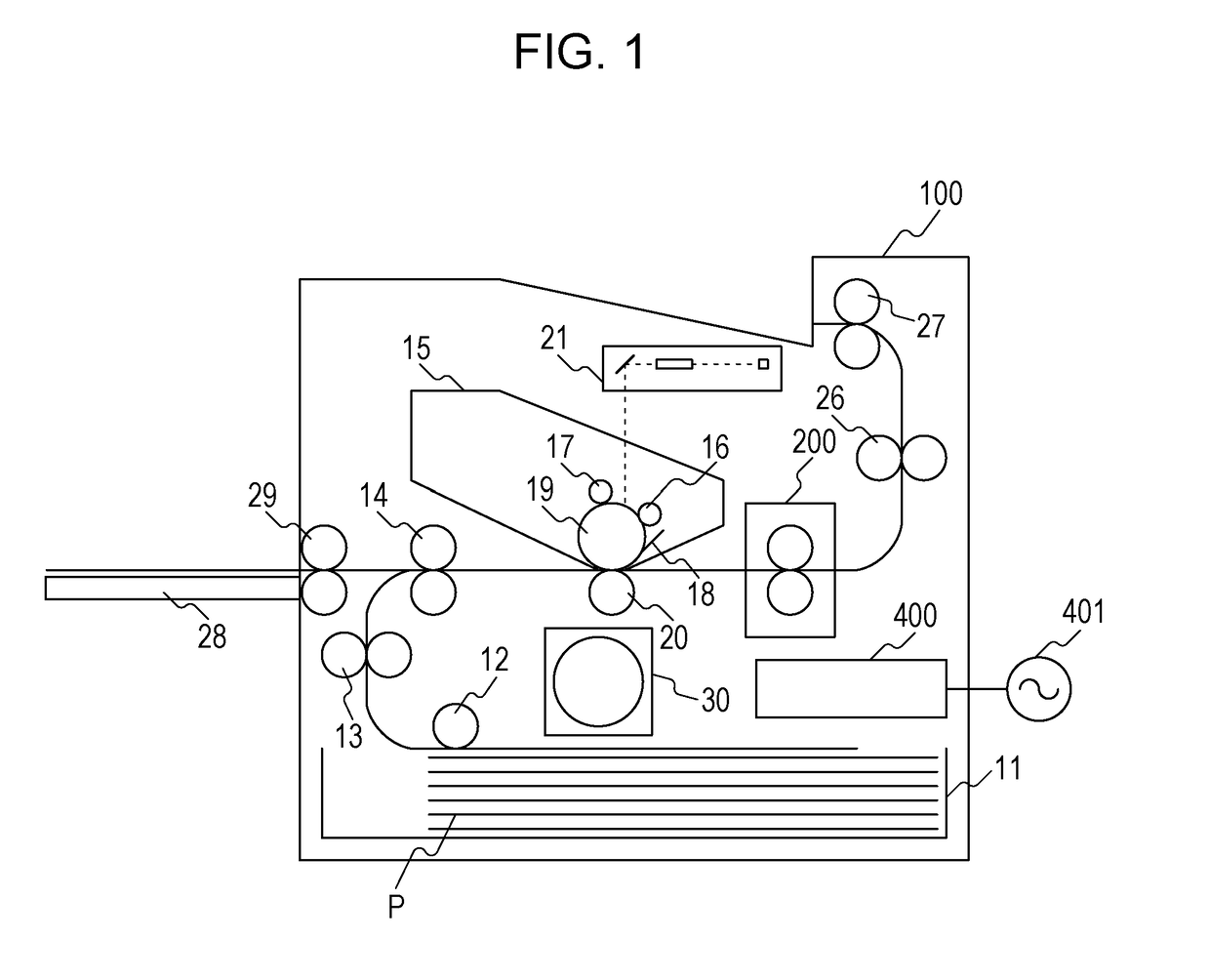
[0023]FIG. 1 is a schematic cross-sectional view of an image forming apparatus 100 according to an exemplary embodiment of the present disclosure. The image forming apparatus 100 of the present exemplary embodiment is a laser printer that forms an image on a recording material using an electrophotographic method. When a print signal is generated, a scanner unit 21 emits a laser beam that has been modulated according to a piece of image information and scans a surface of a photosensitive drum 19 charged with a predetermined polarity with a charge roller 16. With the above, an electrostatic latent image is formed on the photosensitive drum 19. By supplying toner to the electrostatic latent image from a developing roller 17, the electrostatic latent image on the photosensitive drum 19 is developed into a toner image. Meanwhile, recording materials (sheets of recording paper) P stacked in a sheet supplying cassette 11 is fed sheet by sheet with...

second exemplary embodiment

[0056]A second exemplary embodiment of the present invention will be described. The basic configuration and operation of the image forming apparatus of the second exemplary embodiment are the same as those of the first exemplary embodiment. Accordingly, elements and configurations that have the same or corresponding functions as those of the first exemplary embodiment will be attached with the same reference numerals and detailed description thereof will be omitted. Matters that are not particularly described in the second exemplary embodiment is similar to those of the first exemplary embodiment.

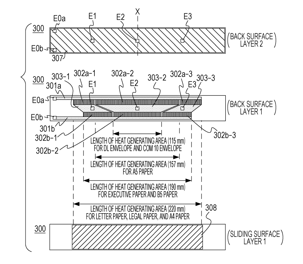
[0057]Referring to FIGS. 7A to 7C, a configuration of a heater (a heater 800) used in the second exemplary embodiment will be described in detail. FIG. 7A is a cross-sectional view of the heater 800. FIG. 7B illustrates plan views of layers of the heater 800. FIG. 7C is a diagram illustrating a positional relationship of the heat generating areas. While in the first exemplary embodiment, th...

third exemplary embodiment

[0068]A third exemplary embodiment of the present invention will be described. The basic configuration and operation of the image forming apparatus of the third exemplary embodiment are the same as those of the first exemplary embodiment. Accordingly, elements and configurations that have the same or corresponding functions as those of the first exemplary embodiment will be attached with the same reference numerals and detailed description thereof will be omitted. Matters that are not particularly described in the third exemplary embodiment is similar to those of the first exemplary embodiment.

[0069]Referring to FIGS. 9A and 9B, a configuration of a heater (a heater 500) used in the third exemplary embodiment will be described in detail. FIG. 9A is cross-sectional view of the heater 500. FIG. 9B illustrates plan views of layers of the heater 500. In the first exemplary embodiment, the conductor B (the conductor 303) serves as a common conductive path of the group a of heat generatin...


PUM


Abstract

A heater including a substrate, a first heat generating line provided on the substrate and in a longitudinal direction of the substrate, the first heat generating line being divided into a plurality of heat generating blocks in the longitudinal direction, the plurality of heat generating blocks being controllable independently, and a second heat generating line provided on the substrate and in the longitudinal direction of the substrate, the second heat generating line being divided into a plurality of heat generating blocks in the longitudinal direction, the plurality of heat generating blocks being controllable independently. In the heater, divided positions of the first heat generating line and divided positions of the second heat generating line are different.

Description

BACKGROUND[0001]Field[0002]The present disclosure relates to an image heating apparatus, such as a fixing device mounted in an image forming apparatus including a copier and a printer employing an electrophotographic method or an electrostatic recording method, or a glossing device that improves a gloss of a toner image by reheating a fixed toner image on a recording material. Furthermore, the present disclosure relates to a heater used in the image heating apparatus.[0003]Description of the Related Art[0004]There is a device, serving as an image heating apparatus, including a cylindrical film, a heater that is in contact with an inner surface of the heater, and a roller that forms a nip portion together with the heater with the film in between. When small-sized sheets are continuously printed in the image forming apparatus in which the image heating apparatus is mounted, a phenomenon (a sheet non-passing portion temperature rise) in which temperature in the areas of the nip portion...

Claims


Application Information

Patent Timeline
Patent Type & Authority Applications(United States)
IPC IPC(8): H05B1/00H05B1/02H05B3/00
CPCG03G15/2039H05B1/02G03G15/2053H05B3/0095G03G15/2042H05B1/0241H05B3/265H05B2203/011
Inventor MOCHIZUKI, KEISUKEIWASAKI, ATSUSHISAKO, MASATO
Owner CANON KK
Why Eureka
Try Eureka