Check patentability & draft patents in minutes with Patsnap Eureka AI!

Shuttle valve with durable soft seal

a shuttle disk and sealing technology, applied in the field of shuttle disks, can solve the problems of valve wear and premature failure, valve replacement, and hydrocarbon formation piercing by the well bore, and achieve the effect of sealing against the shuttle disk

Active Publication Date: 2017-03-16
PROSERV GILMORE VALVE LLC
View PDF6 Cites 1 Cited by
  • Summary
  • Abstract
  • Description
  • Claims
  • Application Information

AI Technical Summary

Benefits of technology

The patent text describes a cage that is secured in a bore using inlet adaptors and shuttle disks. The shuttle disks may be made of a different material than the inlet adaptors, which helps to seal against the shuttle disk. The technical effect of this invention is the secure installation of a cage in a bore, which reduces the risk of leaks or other issues during use.

Problems solved by technology

The blowout preventer(s) may include hydraulic rams located on opposed sides of the well bore opening, which close and seal off the well bore when an abnormal pressure condition is encountered and there is a risk that the pressure of the hydrocarbon formation pierced by the well bore exceeds the pressure imposed on those fluids by the weight of the drilling mud in the well bore.
This can cause wear and premature failure, and the need to replace, the valve.

Method used


Image

  • Shuttle valve with durable soft seal
  • Shuttle valve with durable soft seal
  • Shuttle valve with durable soft seal

Examples


Embodiment Construction

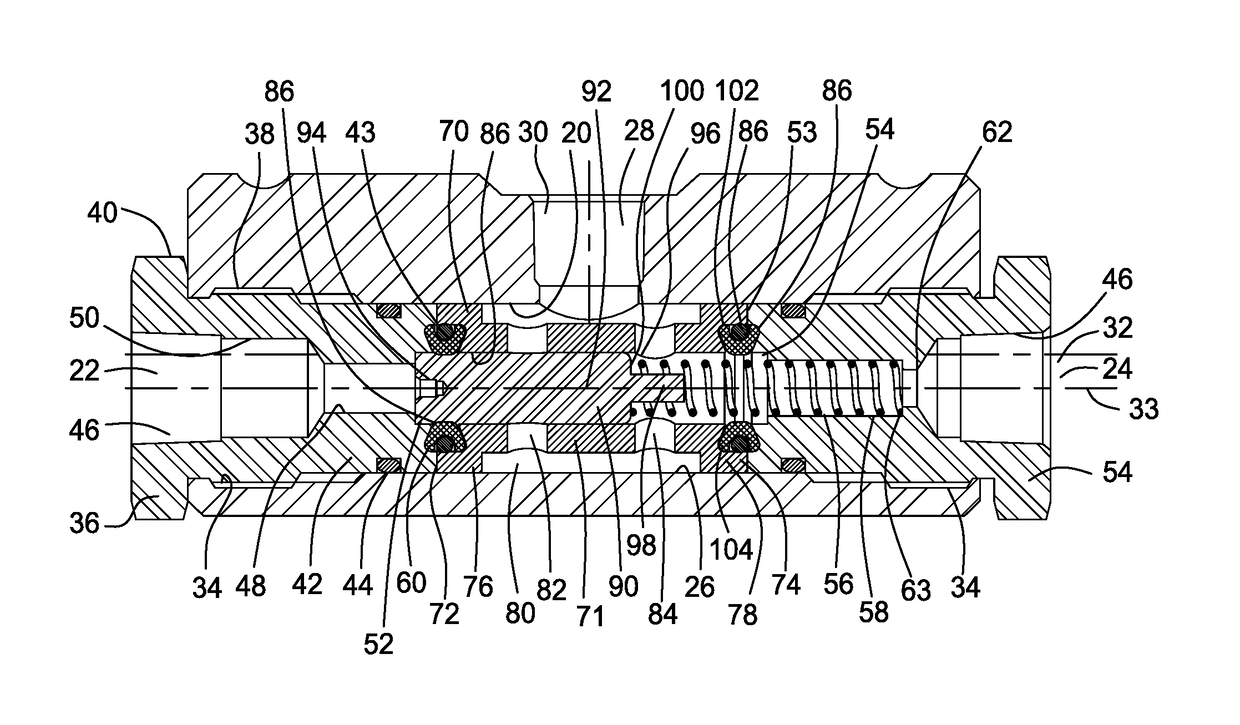
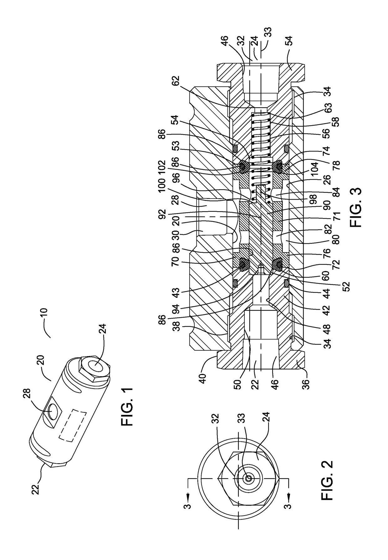
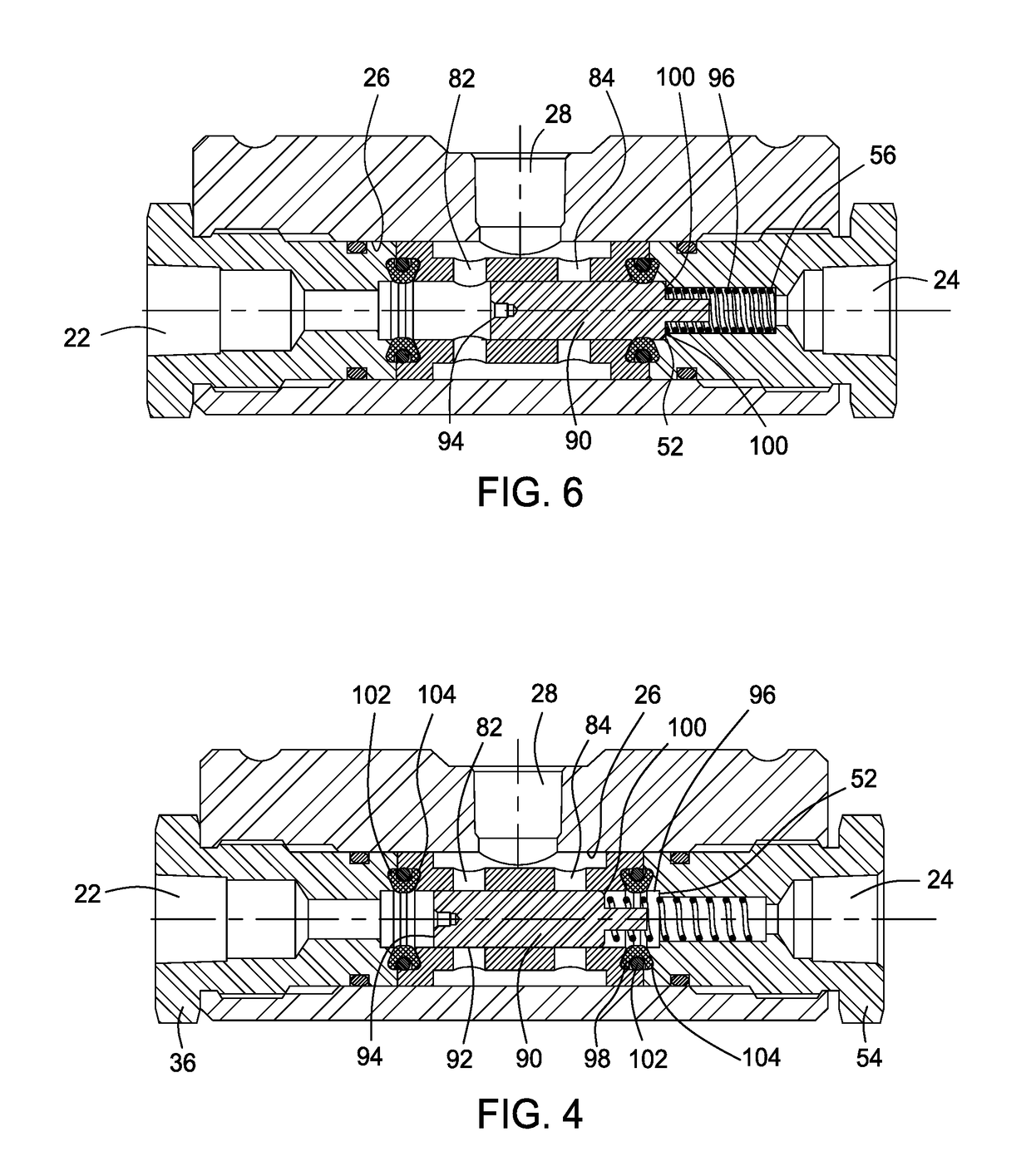
[0027]Referring to FIGS. 1 to 3, a shuttle valve 10 is provided with a body 20 having a first inlet 22 on a first side thereof, a second inlet 24 on a second, opposed, side thereof, and a through bore 26 extending directly between the first and second inlets 22, 24. An outlet 28 is configured with a bore 30 extending through the side wall of the body 20 generally perpendicular to the direction of the through bore 26. The body 20 is generally configured as a right circular cylinder, whereby the centerline 32 of the cylinder is offset from, and generally parallel to, the centerline 33 of the through bore 26.

[0028]Each of inlets 22, 24 includes a threaded bore 34 having a first diameter, and terminating at the through bore 26, which has a second diameter smaller than that of the threaded bores 34. An inlet adaptor is threaded into the threaded bores 34 of each inlet 22, 24. The first inlet adaptor 36 is received in the first inlet 22 and includes a threaded outer wall 38 bounded by a h...


PUM


Abstract

A shuttle valve having a cage fixed in the cross bore thereof by opposed inlet adaptors extending into opposed first and second inlets is provided. A shuttle is reciprocally located in a bore in the cage, to selectively seal one of the first or second inlets from fluid communication with the valve outlet. The shuttle may be spring biased to maintain one of the inlets in the closed position without the need to apply a pressure into an inlet of the valve.

Description

BACKGROUND OF THE INVENTION[0001]Field of the Invention[0002]The present invention relates to the field of valves. More particularly, the invention relates to the field of shuttle valves operable to pass fluid thereinto from one of two inlets, based on the pressure at the inlets, and pass that fluid therethrough to a valve outlet. Such valves provide both primary and backup fluid availability to a device to which they are ported, such as the control logic circuits of a blowout preventer, including a blowout preventer located in a subsea environment.[0003]Description of the Related Art[0004]Systems for closing off the bore of a well being drilled or completed in the event of an overpressure condition in the well bore typically include one or more blowout preventers, at least two or more pressure sources such as accumulators, and one or more control valves arranged between the pressure source and the blowout preventer. The blowout preventer(s) may include hydraulic rams located on opp...

Claims


Application Information

Patent Timeline
Patent Type & Authority Applications(United States)
IPC IPC(8): G05D16/10E21B33/064F16K11/07
CPCG05D16/106E21B33/061E21B33/064F16K11/0716F16K11/044F16K11/0712F16K17/0473E21B34/16
Inventor PATTERSON, ANDYMARTINEZ, GERARDO
Owner PROSERV GILMORE VALVE LLC
Features
  • R&D
  • Intellectual Property
  • Life Sciences
  • Materials
  • Tech Scout
  • Unparalleled Data Quality
  • Higher Quality Content
  • 60% Fewer Hallucinations
Learn More