Vessel Prosthesis

a technology for prostheses and vessels, applied in the field of valve prosthesis, can solve the problems of relatively rough/sharp stent ends, damage to vessels, etc., and achieve the effect of reducing or eliminating any relatively sharp or rough edges

Active Publication Date: 2017-03-23
TERUMO KK
View PDF4 Cites 192 Cited by
  • Summary
  • Abstract
  • Description
  • Claims
  • Application Information

AI Technical Summary

Benefits of technology

[0005]One aspect of the present invention is directed to techniques and embodiments that reduce or eliminate any relatively sharp or rough edges created from wire ends of a braided stent. For example, the wire ends of a stent can be terminated in an end cap or by bending and welding the stent's wires.

Problems solved by technology

However, when a stent is machine-braided, its wires must typically be cut at its distal and proximal ends, creating relatively rough / sharp stent ends.
Whether hand-braided or machine-braided, sharp stent ends can cause damage to the vessels as it is deployed and therefore is undesirable.

Method used


Image

  • Vessel Prosthesis
  • Vessel Prosthesis
  • Vessel Prosthesis

Examples


Embodiment Construction

[0019]Specific embodiments of the invention will now be described with reference to the accompanying drawings. This invention may, however, be embodied in many different forms and should not be construed as limited to the embodiments set forth herein; rather, these embodiments are provided so that this disclosure will be thorough and complete, and will fully convey the scope of the invention to those skilled in the art. The terminology used in the detailed description of the embodiments illustrated in the accompanying drawings is not intended to be limiting of the invention. In the drawings, like numbers refer to like elements.

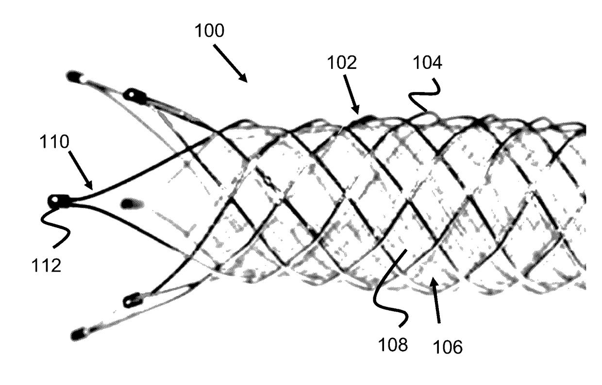
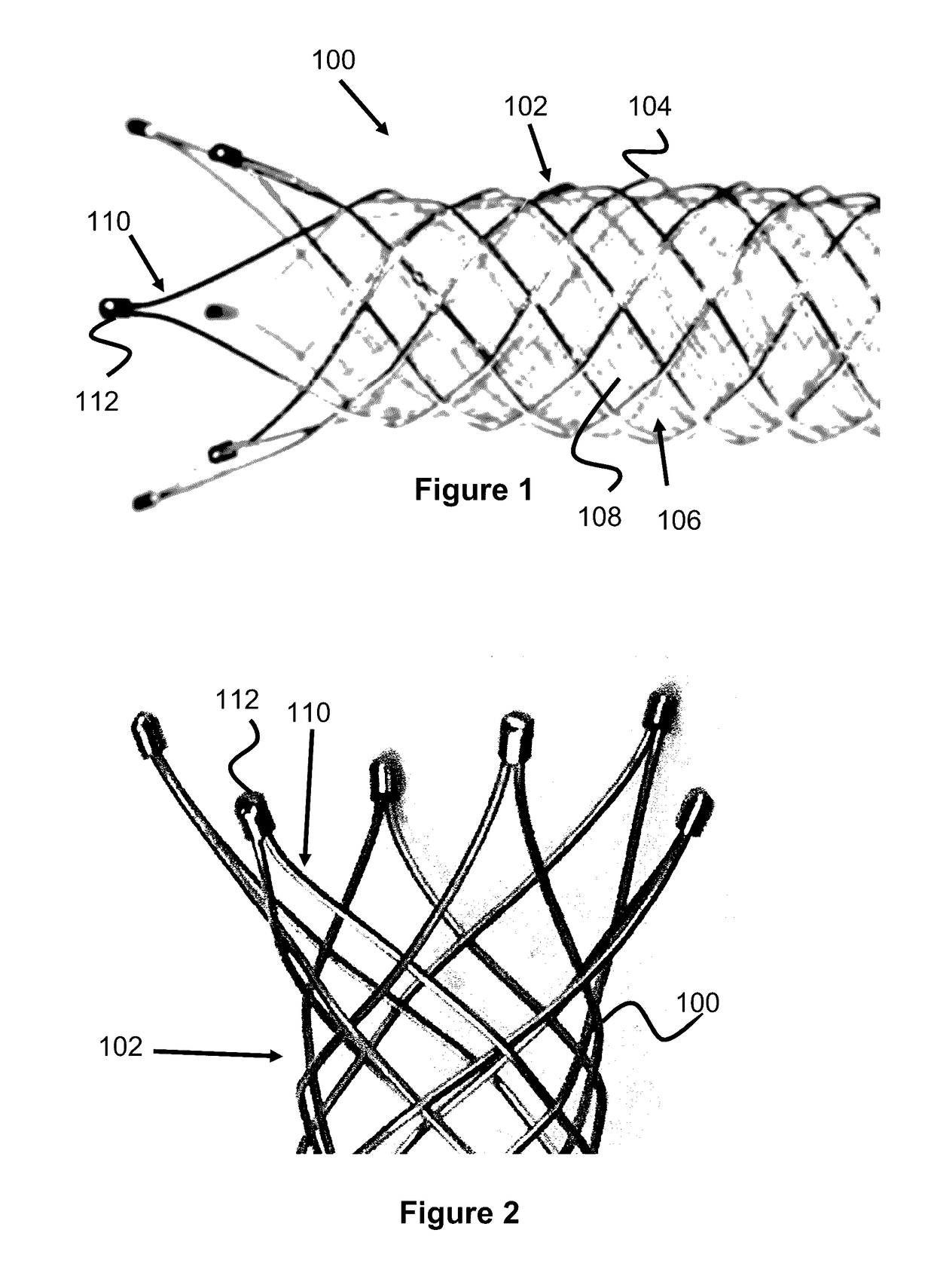
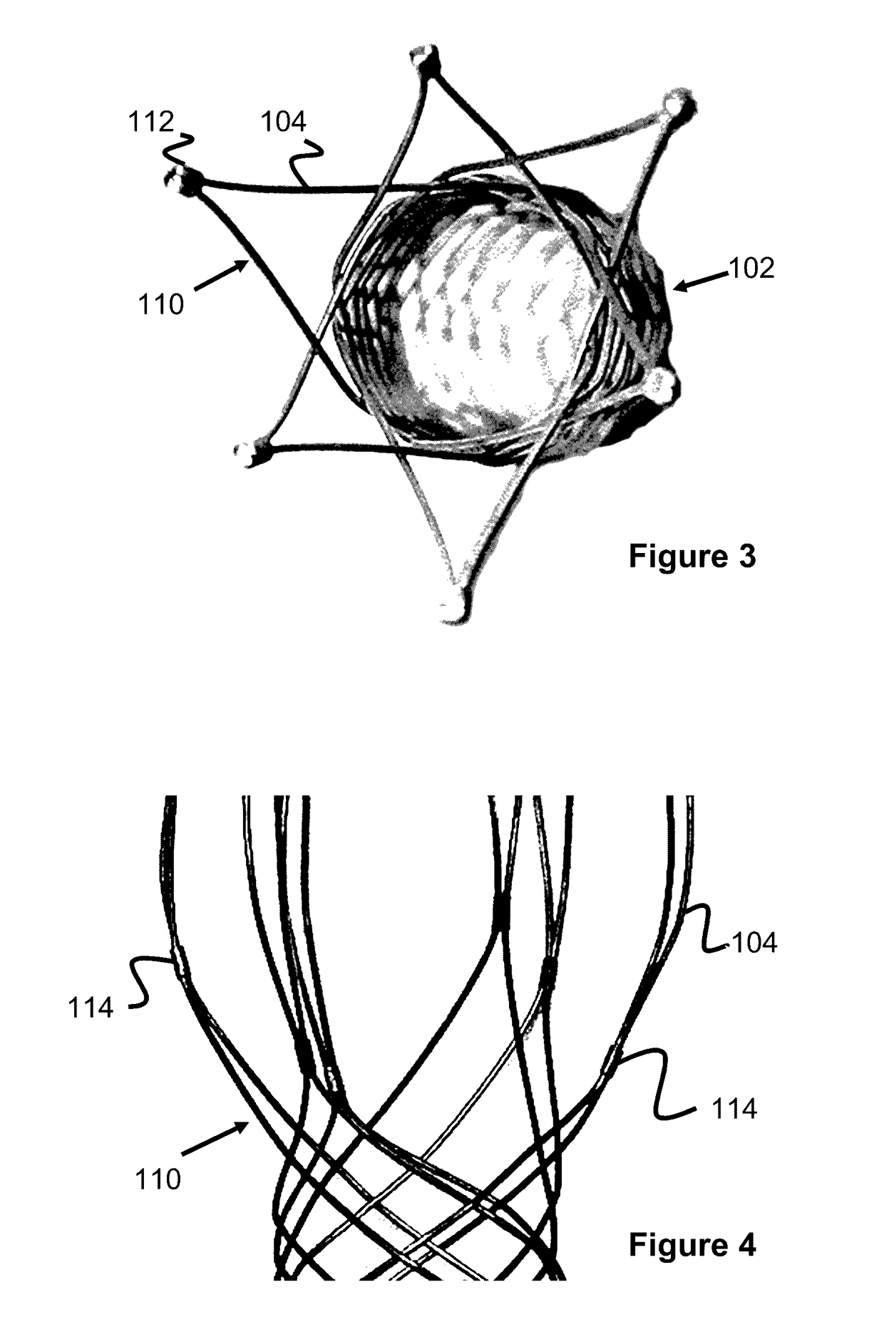
[0020]Stents, stent-grafts, or other vascular prostheses (herein referred to as stents for simplicity) are sometimes formed of one or more wires that are braided into a tubular structure. When these devices are braided by hand, the wire can be braided so as to terminate along the length of the stent instead of at the stent's proximal or distal ends. As a resul...


PUM


Abstract

A vascular prosthesis is described, having blunted wire ends. The blunted wire ends can take on a variety of configurations including end caps, bent ends, curved ends, or eyelets. The novel ends provide a smooth surface to contact the blood vessel walls thereby reducing the risk of trauma during placement of the prosthesis.

Description

RELATED APPLICATIONS[0001]This application claims benefit of U.S. Provisional Application Ser. No. 62 / 220,895 filed Sep. 18, 2015 entitled Vessel Prosthesis, which is hereby incorporated herein by reference in its entirety.BACKGROUND OF THE INVENTION[0002]Vascular prostheses such as stents and / or stent-grafts are used for a variety of reasons in the vasculature. For example, they can be used to prop open blood vessels, treat plaque buildup, replace a portion of a blood vessel, divert blood flow away from a target area, provide a scaffold or lumen for the introduction of other medical devices, or for various other reasons.[0003]It is desirable for these devices to have significant strength and to be able to effectively anchor within a blood vessel in order to remain expanded and to prevent migration from a target area after deployment. These devices must also be track-able through a delivery device (i.e. a catheter) without too much friction so that they can be delivered to a target ...

Claims


Application Information

Patent Timeline
Patent Type & Authority Applications(United States)
IPC IPC(8): A61F2/90
CPCA61F2240/001A61F2/90A61F2230/0054
Inventor LAM, CANGVONG, SHIRLEYTSAI, PRISCILLA
Owner TERUMO KK
Why Eureka
Try Eureka