Stator, brushless motor, stator manufacturing method
a stator and motor technology, applied in the direction of stator/rotor body manufacturing, magnetic circuit shape/form/construction, solid insulation application, etc., can solve the problems of difficult to achieve a high density arrangement of coils, reduce the size of rotating machines, and reduce the speed of coil winding when employing a nozzle machin
- Summary
- Abstract
- Description
- Claims
- Application Information
AI Technical Summary
Benefits of technology
Problems solved by technology
Method used
Image

Examples
third exemplary embodiment
of the Present Invention
[0293]Explanation follows regarding a third exemplary embodiment of the present invention, with reference to the drawings.
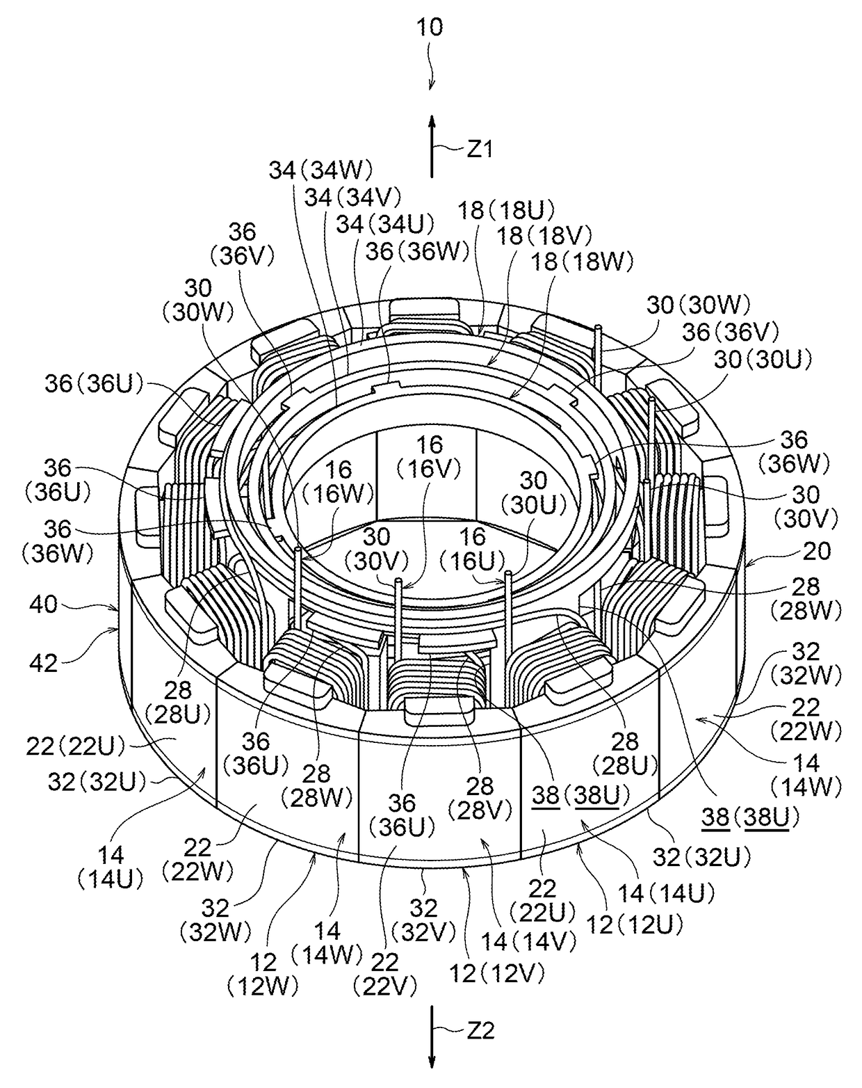
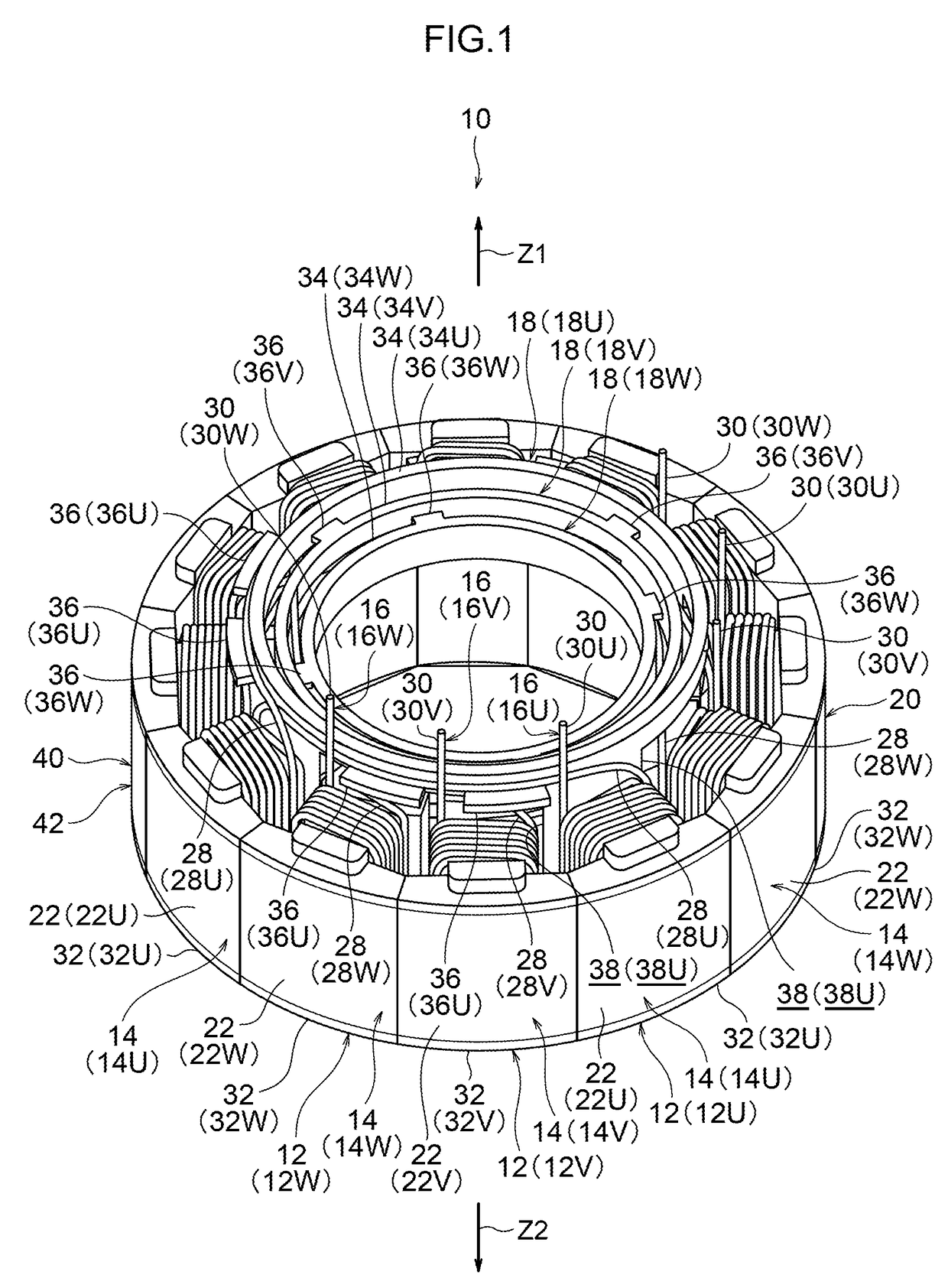
[0294]A stator 310 according to the third exemplary embodiment of the present invention is illustrated in FIG. 21, and is employed for example in an inner rotor type brushless motor, and is configured including a U-Phase stator configuration section 312U, a V-phase stator configuration section 312V and a W-phase stator configuration section 312W, illustrated in FIG. 22A to FIG. 22C.
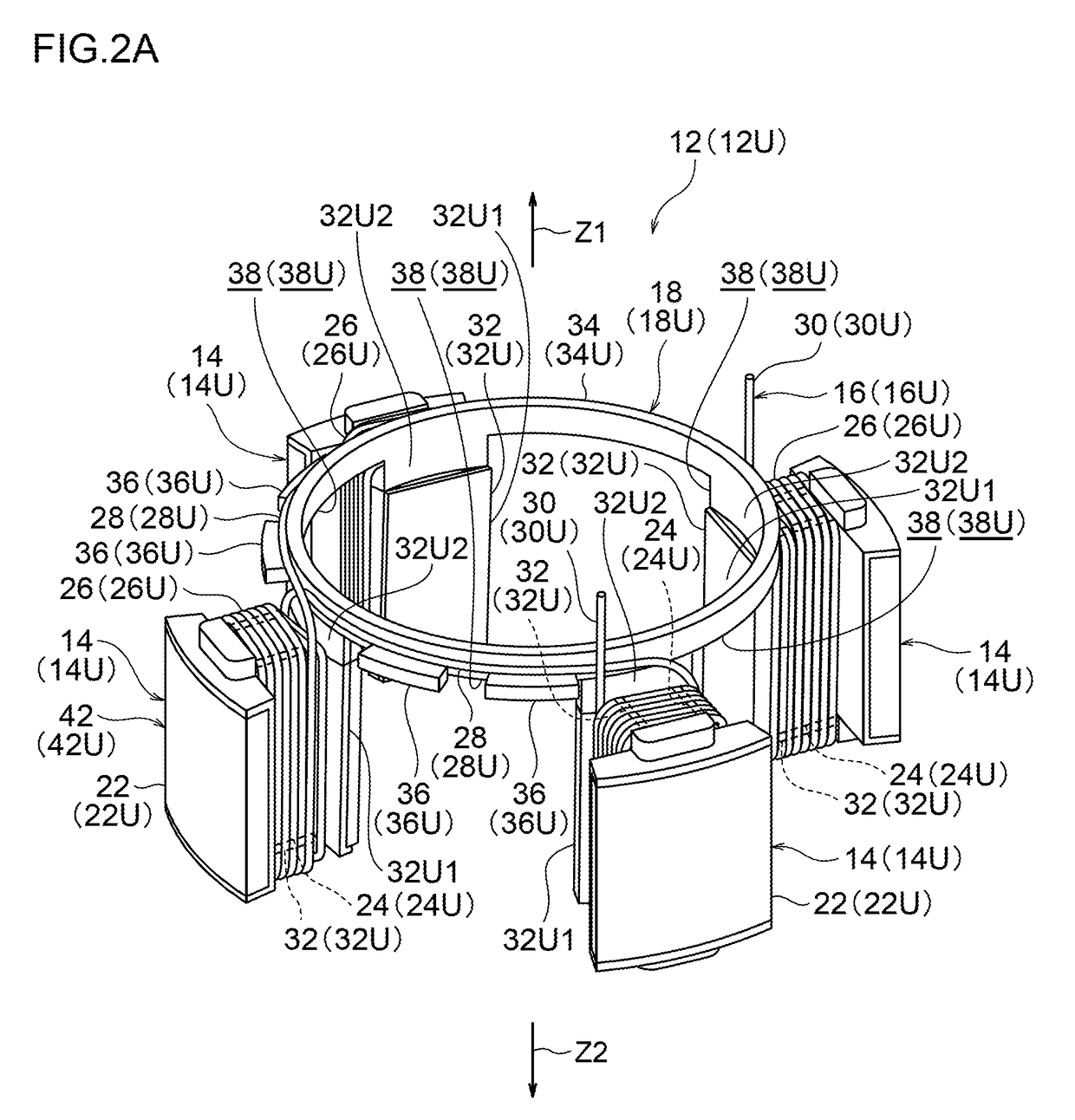
[0295]As illustrated in FIG. 21 and FIG. 22A, the U-phase stator configuration section 312U is configured with plural core configuration sections 314U, a coil wire 316U, and an insulator 318U. Note that the coil wire 316U is omitted from illustration in FIG. 22A.
[0296]The plural core configuration sections 314U configure a stator core 320 together with plural V-phase core configuration sections 314V and plural W-phase core configuration sections 314W, described ...
fourth exemplary embodiment
[0381]Explanation follows regarding a fourth exemplary embodiment of the present invention.
[0382]A stator 410 according to a fourth exemplary embodiment of the present invention illustrated in FIG. 27 has portions similar to those of the stator of the third exemplary embodiment. Explanation hence focusses on differing portions and explanation regarding similar portions is omitted as appropriate.
[0383]In the present exemplary embodiment, as illustrated in FIG. 27 and FIG. 28A, in a U-phase stator configuration section 412U, a first connection portion 436U is disposed at a first axial direction side (the arrow Z1 side) of a stator core 420 and is formed in a ring shape extending around a circumferential direction of the stator core 420. The first connection portion 436U is provided further to a stator core 420 radial direction inside than teeth section insulator portions 442U, 452U (namely, than winding portions 428U wound on teeth sections 422U). Axial direction extending portions 44...
fifth exemplary embodiment
[0422]Explanation follows regarding a fifth exemplary embodiment of the present invention.
[0423]Note that in the following explanation, for convenience the letters U, V, W are omitted as suffixes to the labels of each member and each portion when no discrimination is made between the U-phase, the V-phase and the W-phase.
[0424]The fifth exemplary embodiment of the present invention illustrated in FIG. 34 has an interlocking structure 570 that differs from that of the fourth exemplary embodiment of the present invention in the following respects.
[0425]Namely, fitting portions 572 are formed at one member of adjacent yoke configuration section insulator portions 554, and fitting protrusions 573 are formed to the fitting portions 572. Recess shaped fitted-to portions 574 are moreover formed at the other member of the adjacent yoke configuration section insulator portions 554. Insulator portions 534 of any insulators 518 out of the plural insulators are accordingly fixed together by the ...
PUM
| Property | Measurement | Unit |
|---|---|---|
| projection shape | aaaaa | aaaaa |
| rotational magnetic field | aaaaa | aaaaa |
| diameters | aaaaa | aaaaa |
Abstract
Description
Claims
Application Information
 - Generate Ideas
- Intellectual Property
- Life Sciences
- Materials
- Tech Scout
- Unparalleled Data Quality
- Higher Quality Content
- 60% Fewer Hallucinations
Browse by: Latest US Patents, China's latest patents, Technical Efficacy Thesaurus, Application Domain, Technology Topic, Popular Technical Reports.
© 2025 PatSnap. All rights reserved.Legal|Privacy policy|Modern Slavery Act Transparency Statement|Sitemap|About US| Contact US: help@patsnap.com