Edge Flashing for Roofs with Functional Surface Materials

a functional surface material and roof technology, applied in roof coverings, roofs, constructions, etc., can solve the problems of ponding, not allowing water drainage, and requiring more manufacturing costs, so as to avoid ponding and increase the cost of installation

Active Publication Date: 2017-05-25
ANTHONY ELI
View PDF12 Cites 14 Cited by
  • Summary
  • Abstract
  • Description
  • Claims
  • Application Information

AI Technical Summary

Benefits of technology

[0015]Flashing for use at the edge of roofs or decks that are provided with surface materials are presented. In exemplary embodiments, flashing may be provided at the edge of a roof to retain or provide an edge treatment for an aesthetic and functional surface material, such as, for example, a cast paver, while at the same time allowing for water drainage. In one embodiment, a piece of flashing material contains a leg that is fastened along the edge of the top of a flat roof. This embodiment continues into two legs that form a V-shaped trough which comes off the roofing membrane and has penetrations at the bottom to release water. The outer leg of the “V” most commonly extends to a level higher than the roofing membrane in order to make contact with and edge an installed surface material. Various other shapes and end treatments, including various embodiments providing both an edge flashing as well as an integrated rectangular shaped gutter-like trough are also presented.

Problems solved by technology

These devices, however, do not allow for water drainage if water were to get under the installed surface material.
However, when water is directed by the pitch of the roof towards the outer edges, ponding will occur if the edging system does not allow for that water to pass.
Also, such conventional devices generally consist of two or more parts, making them both more difficult to install and more costly to manufacture—especially devices using extruded components.
If a surface material butts into such a vertical edge, the holes may be partially or completely blocked so that the water may be slow to release and ponding can still occur.
Additionally, the aesthetic of having visible holes along the edge flashing may not be desirable.
Edging with holes in the outer vertical surface may also not account for a variance of pressure applied by the surface material.
Often a roof surface is not perfectly square.
If a conventional vertical edging surface is pressed out by the abutment of an installed surface material, a gap may start to open up between the edging and the surface material.
Such a gap could collect debris over time and become less aesthetically pleasing.
Also, such edging may become noticeably pitched if pressed out by the abutting surface material.
One challenge of such flashing is that there are many different thicknesses of surface material.
Also, if the desired surface material to be installed is not of consistent thickness, gaps under the irregular upper horizontal surface of the flashing could collect debris.

Method used


Image

  • Edge Flashing for Roofs with Functional Surface Materials
  • Edge Flashing for Roofs with Functional Surface Materials
  • Edge Flashing for Roofs with Functional Surface Materials

Examples


Embodiment Construction

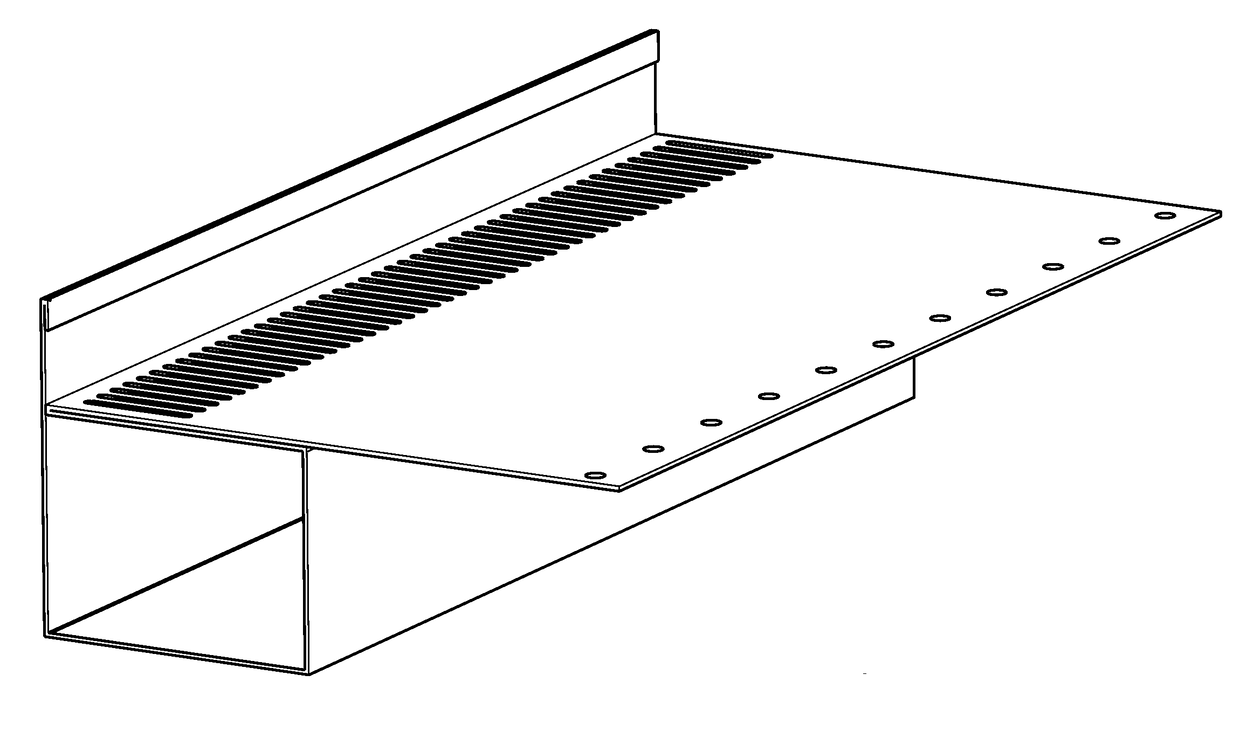
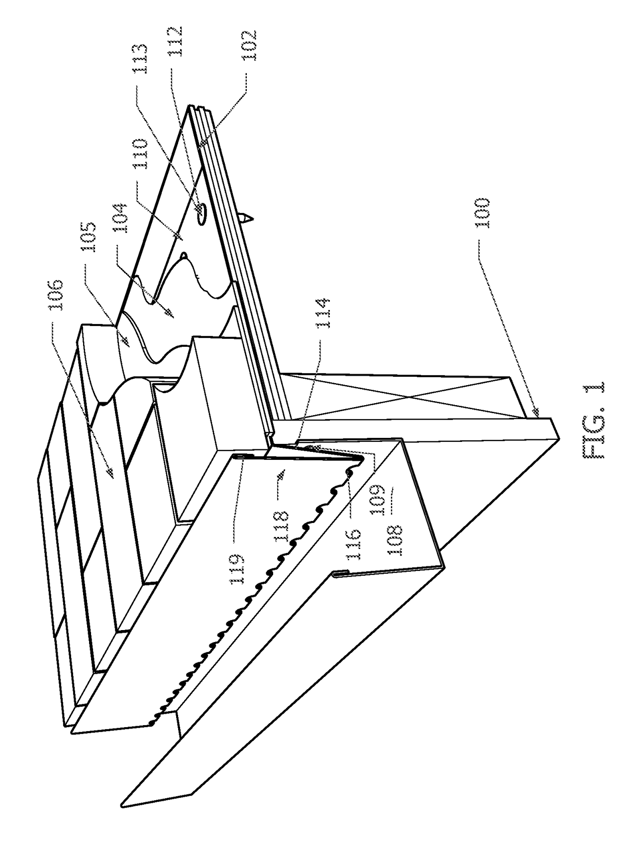
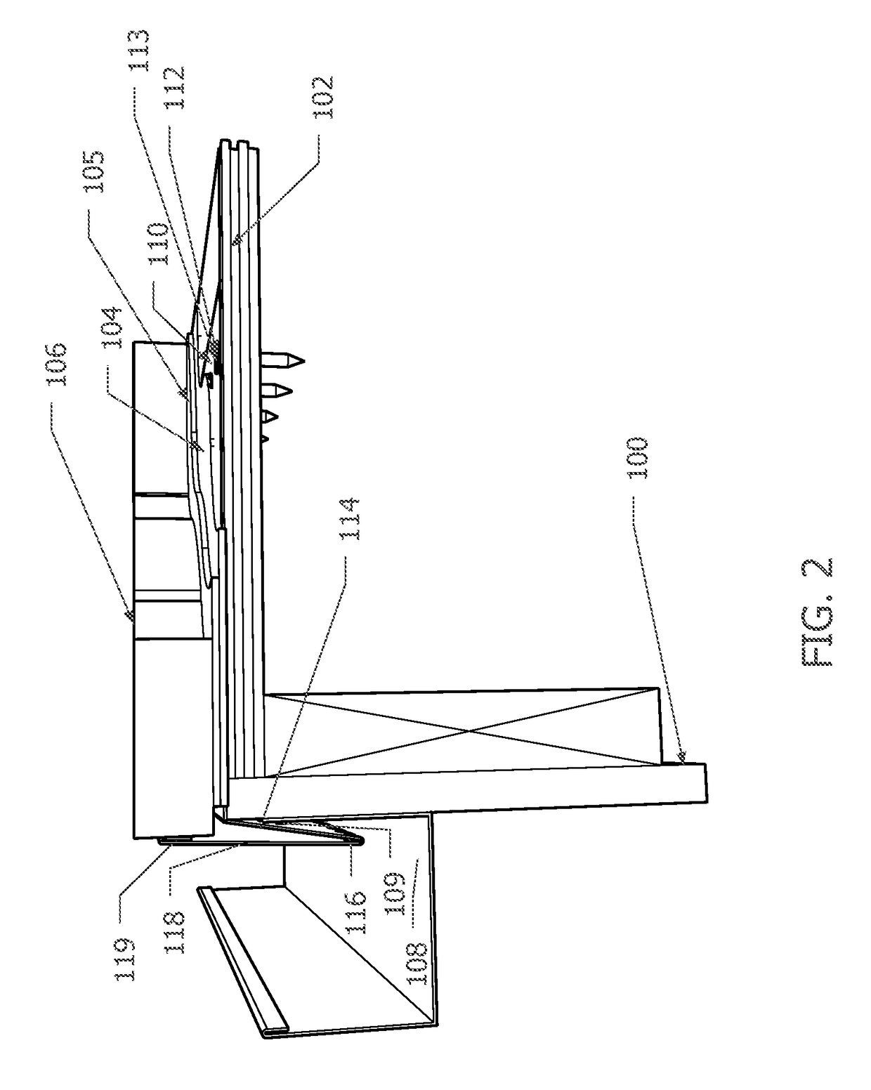
[0057]Various exemplary embodiments of novel types of flashing are described. In exemplary embodiments of the present invention, the flashing can serve as an edging, providing support for an applied surface material on a roof, which in turn provides protection for a roofing membrane. A horizontal (or pitched parallel to the pitch of the underlying roof) leg of the novel flashing can be installed under such an applied surface material, for example, thus augmenting the solidity and longevity of the installation.

[0058]Exemplary flashing can, for example, be installed under a roofing membrane using mechanical fasteners, construction adhesive, or the like, or, for example, it can be installed over the roofing membrane using an adhesive flashing tape (e.g., a marginal strip that is compatible with a given roofing membrane) that overlaps both the flashing and the roofing membrane.

[0059]In exemplary embodiments of the present invention, an exemplary flashing can provide a two-fold approach ...


PUM


Abstract

Flashing for use at the edge of roofs or decks that are provided with surface materials are presented. In exemplary embodiments, flashing may be provided at the edge of a roof to retain or provide an edge treatment for an aesthetic and functional surface material, such as, for example, a cast paver, while at the same time allowing for water drainage. In one embodiment, a piece of flashing material contains a leg that is fastened along the edge of the top of a flat roof. This embodiment continues into two legs that form a V-shaped trough which comes off the roofing membrane and has penetrations at the bottom to release water. The outer leg of the “V” most commonly extends to a level higher than the roofing membrane in order to make contact with and edge an installed surface material. Various other shapes and end treatments, including various embodiments providing both an edge flashing as well as an integrated rectangular shaped gutter-like trough are also presented.

Description

CROSS-REFERENCE TO RELATED APPLICATIONS[0001]The present application claims the benefit of each of U.S. Provisional Patent Application Nos. 62 / 183,547, filed on Jun. 23, 2015 and 62 / 332,302, filed on May 5, 2016, the disclosure of each of which is hereby incorporated herein by reference as if fully set forth.TECHNICAL FIELD[0002]This application relates to roofing and waterproofing materials, and in particular to flashing for use at the edge of flat roofs or pitched to retain or edge an aesthetic and functional surface material such as a cast paver, while at the same time allowing for water drainage.BACKGROUND OF THE INVENTION[0003]Conventionally, when a relatively flat (including slightly pitched) roof is used as a functional balcony or terrace, material is installed over (on top of) the waterproofing membrane / roofing both for aesthetic and practical reasons. Examples of this include a wood deck with non-penetrating framing (sleepers), or a cast paver (such as a split brick paver)....

Claims


Application Information

Patent Timeline
Patent Type & Authority Applications(United States)
IPC IPC(8): E04D13/072E04D13/15E04D13/076
CPCE04D13/0727E04D13/15E04D13/076E04D13/0459E04D13/064E04D2013/0468E04D2013/0472
Inventor ANTHONY, ELI
Owner ANTHONY ELI
Why Eureka
Try Eureka