Three Dimensional LIDAR System With Targeted Field of View

a lidar system and target field technology, applied in the field of three-dimensional lidar systems, can solve the problems of inherently limited device number of pixels it can generate, 3-d point cloud is often required, etc., and achieve the effect of flattening the intensity distribution of light emitted and reducing the peak intensity of light emitted

Active Publication Date: 2017-05-25
VELODYNE LIDAR USA INC
View PDF4 Cites 73 Cited by
  • Summary
  • Abstract
  • Description
  • Claims
  • Application Information

AI Technical Summary

Benefits of technology

[0015]In yet another aspect, an overmolded lens is fixedly coupled to one or more of the light detecting elements. The overmolded lens protects the light detecting element and is shaped to collect incoming light over a larger range of angles than would be possible without the lens.
[0016]In yet another aspect, a lens element is disposed in the light path between a light emitting element and the illumination optics to flatten the intensity distribution of light emitted from the light emitting element. This reduces the peak intensity of light emitted from the LIDAR system.

Problems solved by technology

However, a 3-D point cloud is often required.
The device is inherently limited to the number of pixels it can generate due to the limitation of how many pulses per second are possible from a single laser.

Method used


Image

  • Three Dimensional LIDAR System With Targeted Field of View
  • Three Dimensional LIDAR System With Targeted Field of View
  • Three Dimensional LIDAR System With Targeted Field of View

Examples


Embodiment Construction

[0029]Reference will now be made in detail to background examples and some embodiments of the invention, examples of which are illustrated in the accompanying drawings.

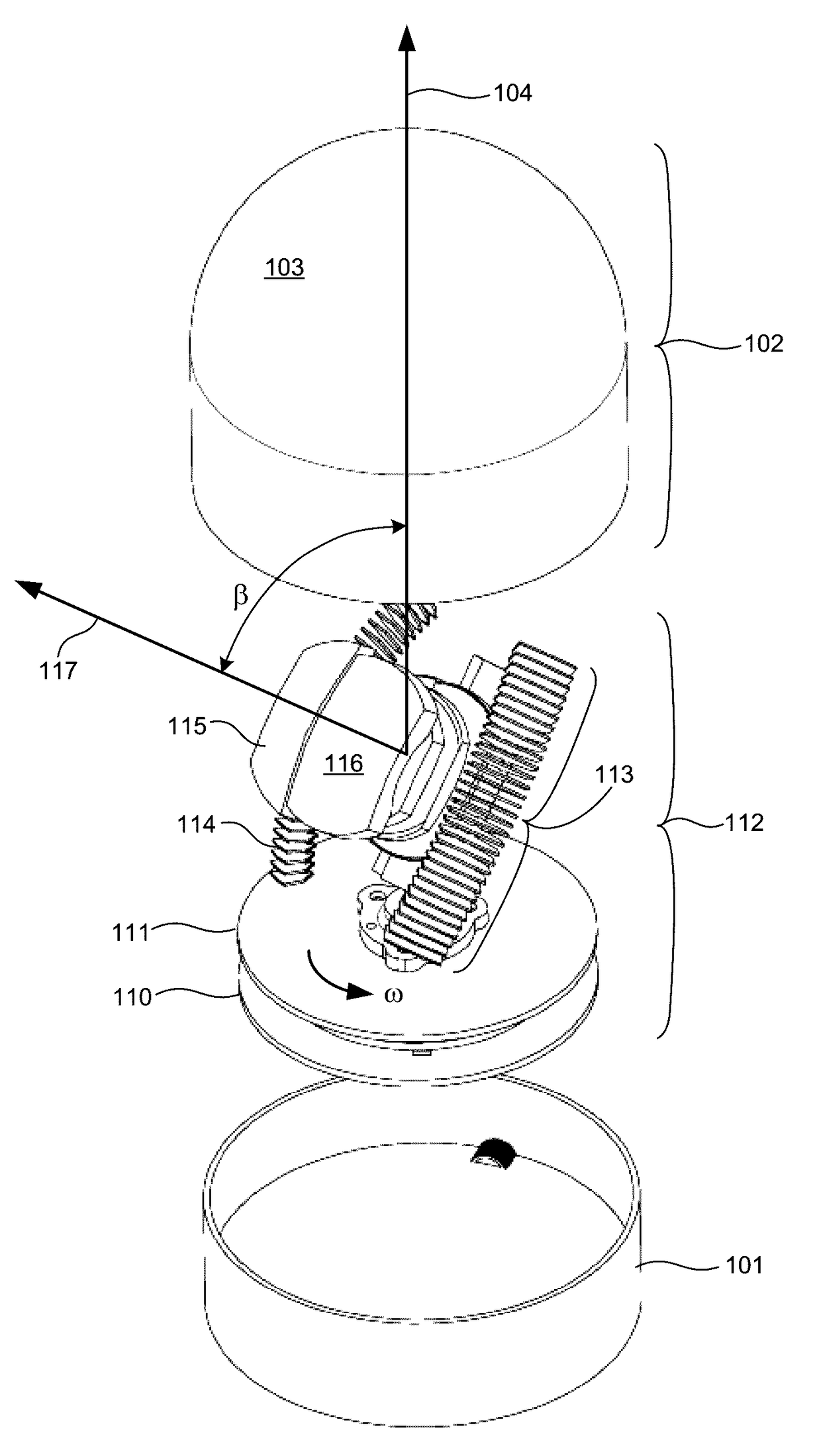
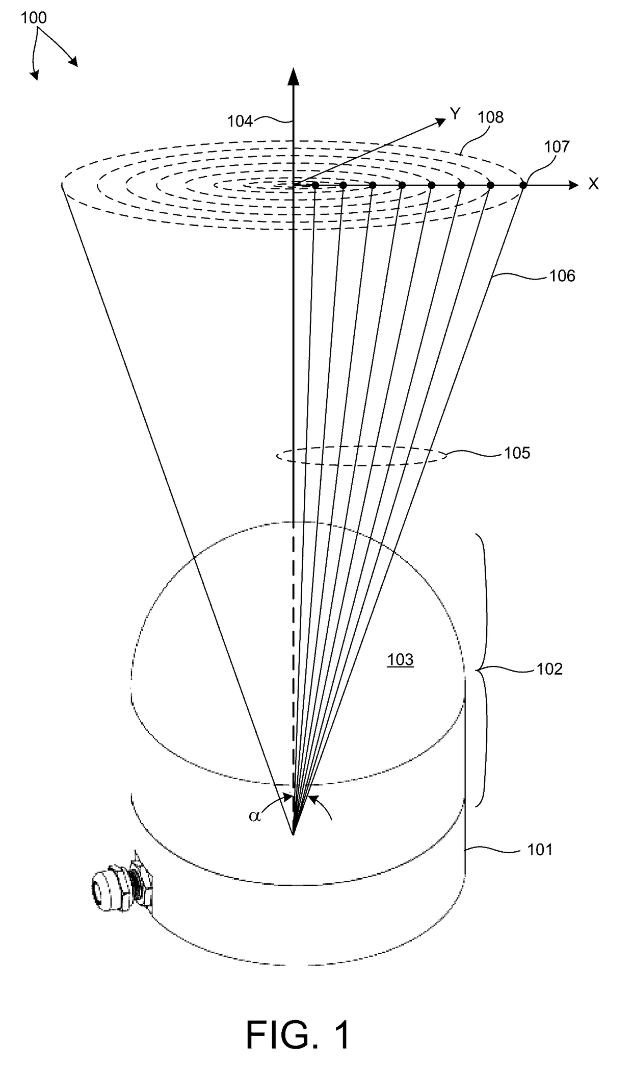
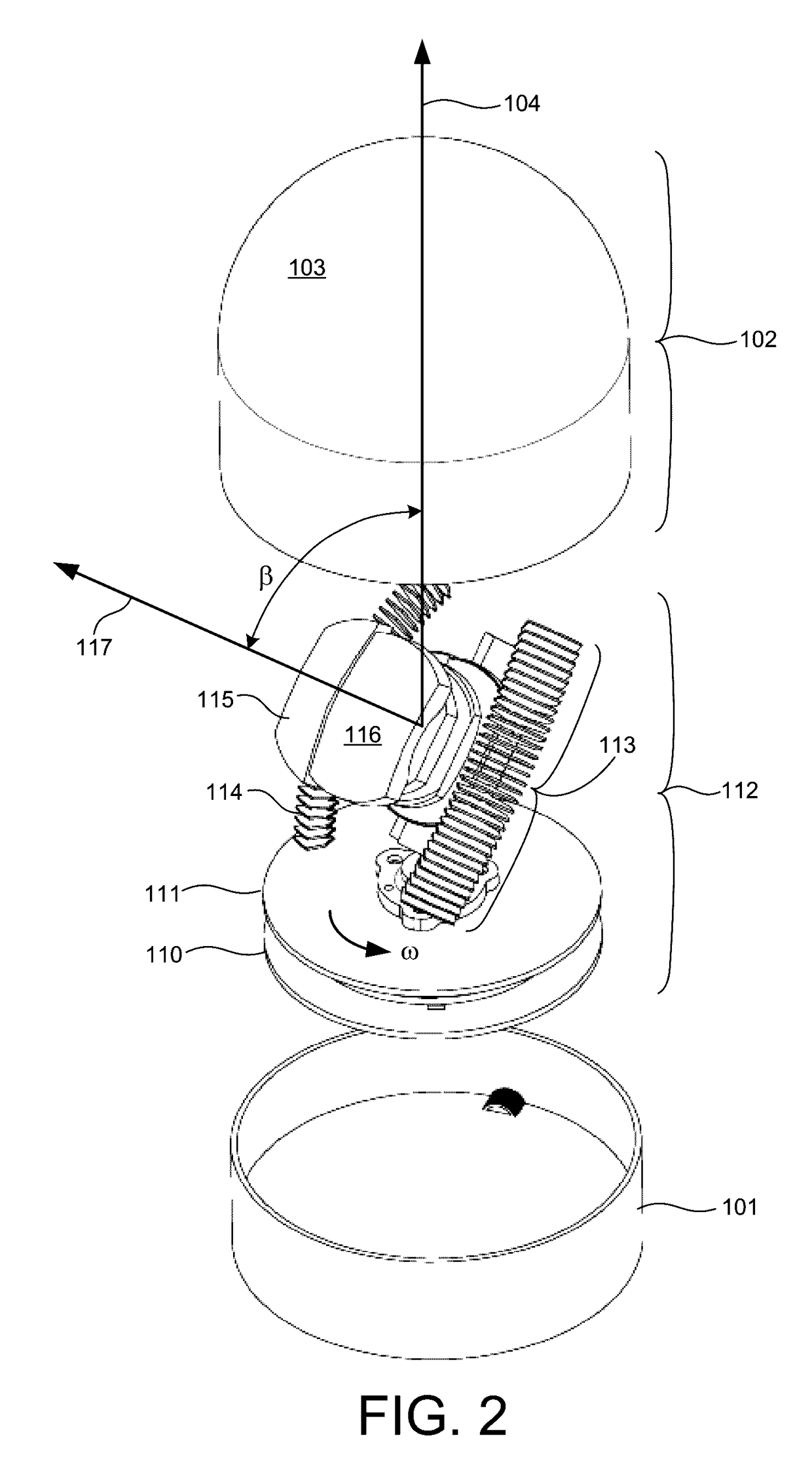
[0030]FIG. 1 is a diagram illustrative of an embodiment of a 3-D LIDAR system 100 in one exemplary operational scenario. 3-D LIDAR system 100 includes a lower housing 101 and an upper housing 102. Lower housing 101 includes a frame structure configured to be attached to an object that is the reference from which LIDAR measurements are made (e.g., a vehicle, a tower, an aircraft, etc.). Upper housing 102 includes a domed shell element 103 constructed from a material that is transparent to infrared light (e.g., light having a wavelength within the spectral range of 700 to 1,700 nanometers). In one example, domed shell element 103 is transparent to light having a narrow range of wavelengths centered at 905 nanometers.

[0031]As depicted in FIG. 1, a plurality of beams of light 105 are emitted from 3-D LIDAR system 100 thro...


PUM


Abstract

A plurality of beams of illumination light are emitted from a LIDAR device over a range of angles and scanned about an axis of rotation. The range of angles includes the axis of rotation. Intermediate electronics boards provide mechanical support and electrical connectivity between a rotating electronics board and various elements of a light emission and collection engine. One or more of the optical elements of the collection optics, the illumination optics, or both, is constructed from one or more materials that absorb light outside of a predetermined wavelength range. An overmolded lens is fixedly coupled to one or more of the light detecting elements to collect incoming light over a larger range of angles. A lens element is disposed in the light path between a light emitting element and the illumination optics to flatten the intensity distribution of light emitted from the light emitting element to reduce peak intensity.

Description

CROSS REFERENCE TO RELATED APPLICATION[0001]The present application for patent claims priority under 35 U.S.C. §119 from U.S. provisional patent application Ser. No. 62 / 260,205, entitled “Three Dimensional LIDAR System With Targeted Field of View,” filed Nov. 25, 2015, the subject matter of which is incorporated herein by reference in its entirety.TECHNICAL FIELD[0002]The described embodiments relate to three dimensional LIDAR systems.BACKGROUND INFORMATION[0003]LIDAR systems employ pulses of light to measure distance to an object based on the time of flight (TOF) of the pulsed of light. A pulse of light emitted from a light source of the LIDAR system interacts with a distal object. A portion of the light reflects from the object and returns to a detector of the LIDAR system. Based on the time elapsed between emission of the pulse of light and detection of the returned pulse of light, a distance is estimated.[0004]In some examples, a pulsed laser emitter is employed to generated lig...

Claims


Application Information

Patent Timeline
Patent Type & Authority Applications(United States)
IPC IPC(8): G01S7/481G01S7/486G01S17/06G01S7/4865G01S17/10G01S17/89
CPCG01S7/4815G01S7/4865G01S17/06G01S7/4817G01S17/10G01S17/89G01S7/4813
Inventor HALL, DAVID S.REKOW, MATHEW NOELNESTINGER, STEPHEN S.KERSTENS, PIETER J.
Owner VELODYNE LIDAR USA INC
Why Eureka
Try Eureka