Multipolarized signal terminal connector for accessory, accessory shoe device, image pickup apparatus, and accessory

Active Publication Date: 2017-08-03
CANON KK
View PDF9 Cites 1 Cited by
  • Summary
  • Abstract
  • Description
  • Claims
  • Application Information

AI Technical Summary

Benefits of technology

The present invention introduces a connector for an accessory device that can be attached to a shoe. This connector allows for the transmission of signals between the accessory device and a camera or other equipment. Additionally, the invention provides an accessory shoe device, an image pickup apparatus, and an accessory that can be connected to the connector. Overall, the invention improves the overall performance and reliability of the accessory system.

Problems solved by technology

However, to realize a narrow pitch of the connection terminals, it is necessary to improve the accuracy in positioning the engagement portion of the accessory shoe device and the signal terminal connector for the electronic viewfinder so as to prevent a short circuit between the connection terminals adjacent to each other, which is by no means easy to achieve.

Method used


Image

  • Multipolarized signal terminal connector for accessory, accessory shoe device, image pickup apparatus, and accessory
  • Multipolarized signal terminal connector for accessory, accessory shoe device, image pickup apparatus, and accessory
  • Multipolarized signal terminal connector for accessory, accessory shoe device, image pickup apparatus, and accessory

Examples


Embodiment Construction

[0034]The present invention will now be described in detail below with reference to the accompanying drawings showing embodiments thereof.

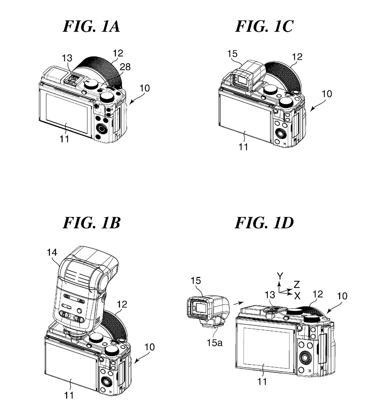
[0035]FIGS. 1A to 1D are views of an image pickup apparatus according to an embodiment. FIG. 1A is a rear perspective view of the image pickup apparatus, and FIG. 1B is a rear perspective view of the image pickup apparatus with an external strobe device attached thereto. Further, FIG. 1C is a rear perspective view of the image pickup apparatus with an external display device attached thereto, and FIG. 1D is a view showing how the external display device is attached to an accessory shoe device of the image pickup apparatus.

[0036]As shown in FIG. 1A, the image pickup apparatus, denoted by reference numeral 10, is provided with a lens barrel 12 for taking an object image into an image pickup device, not shown, a liquid crystal monitor 11, the accessory shoe device (hereinafter simply referred to as “the accessory shoe”), denoted by reference numeral ...


PUM


Abstract

A multipolarized signal terminal connector for an accessory, which is applied to an accessory shoe device having a defined shape. The signal terminal connector includes a first surface opposed to an attaching direction of an accessory, a first terminal row provided the first surface, a second surface which is inclined with respect to the first surface by a predetermined angle, and a second terminal row provided in the second surface. The second surface is inclined with respect to the first surface, in a predetermined direction orthogonal to the attaching direction of the accessory and a direction in which the terminals of the second terminal row are arranged, and is displaced with respect to the first surface in the predetermined direction.

Description

BACKGROUND OF THE INVENTION[0001]Field of the invention[0002]The present invention relates to a signal terminal connector for an accessory, which is applied to an accessory shoe device to which an accessory is attached, an accessory shoe device to which the signal terminal connector for an accessory is applied, an image pickup apparatus, and an accessory.[0003]Description of the Related Art[0004]As an image pickup apparatus, there has been known an image pickup apparatus equipped with an accessory shoe device to which a photographic accessory (hereinafter simply referred to as “the accessory”) can be attached. The accessory shoe device of the image pickup apparatus is provided with an engagement portion for attachment of an accessory and an electric connection portion. In recent years, not only an external strobe device, but also various accessories can be attached to the accessory shoe device of the image pickup apparatus.[0005]Examples of these accessories include an electronic vi...

Claims


Application Information

Patent Timeline
IPC IPC(8): H04N5/232H01R13/24H04N5/225H01R13/639H01R13/652H01R12/77H01R13/629G03B17/56
CPCH04N5/23293H01R12/777H01R13/2442H04N5/2256H01R13/639H01R12/775H01R13/652H01R13/629G03B17/56G03B17/566H04N23/56H04N23/51G03B15/0421H04N23/55
Inventor IWAI, KEITA
Owner CANON KK
Why Eureka
Try Eureka