
Stop Valve

Inactive Publication Date: 2017-08-24
SOLEN ELECTRIC +1
View PDF0 Cites 0 Cited by
  • Summary
  • Abstract
  • Description
  • Claims
  • Application Information

AI Technical Summary

Benefits of technology

The present invention is a stop valve with two seal rings and two retaining grooves in its shaft body. The benefits of this design are that the seal rings are directly formed in the retaining grooves, increasing their strength of combination and preventing detachment under high fluid pressure, which can cause leakage. This results in better safety and performance of the stop valve. Additionally, the design provides a fixing portion for each retaining groove and a fixing section for each seal ring, further increasing the strength of combination. Overall, the invention provides a better solution for preventing fluid leakage and improving safety and performance of the stop valve.

Problems solved by technology

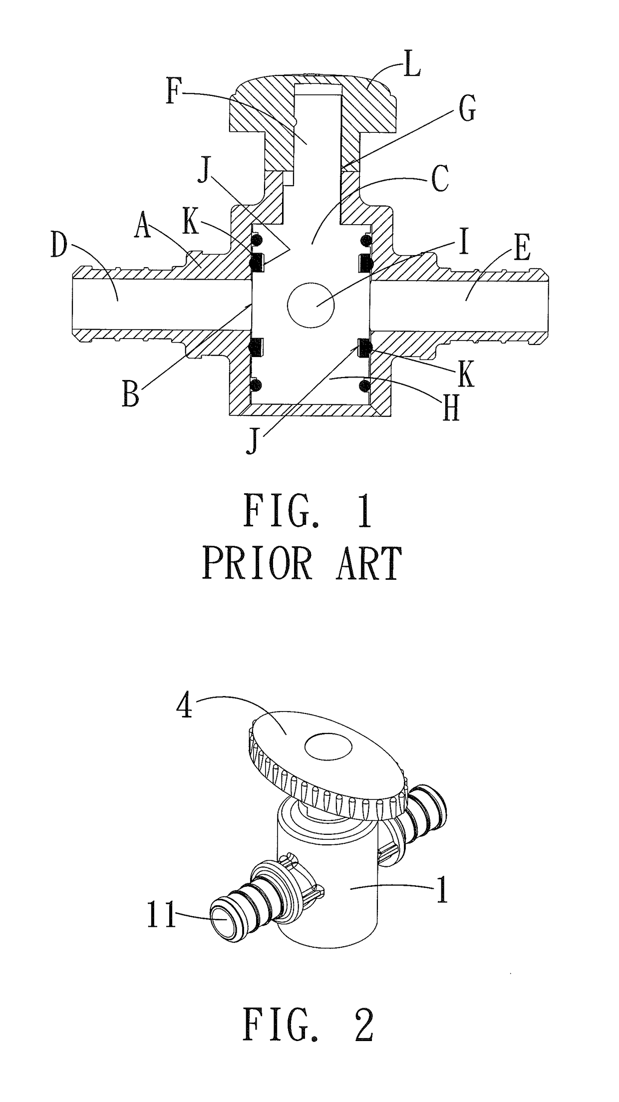
However, the seal rings “K” are loosely received in the retaining grooves “J” so that when the fluid passing through the first channel “D” and the second channel “E” of the valve body “A” is under a high pressure, the seal rings “K” are easily detached from the retaining grooves “J” due to flush of the fluid at the high pressure, thereby easily causing a leak.
In addition, when the shaft “C” is rotated, the seal rings “K” are easily moved or even broken due to frequent compression of the shaft “C”, thereby easily causing a leak.

Method used


Image

  • Stop Valve
  • Stop Valve
  • Stop Valve

Examples


Embodiment Construction

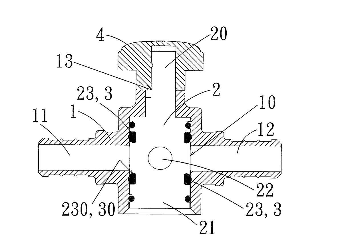
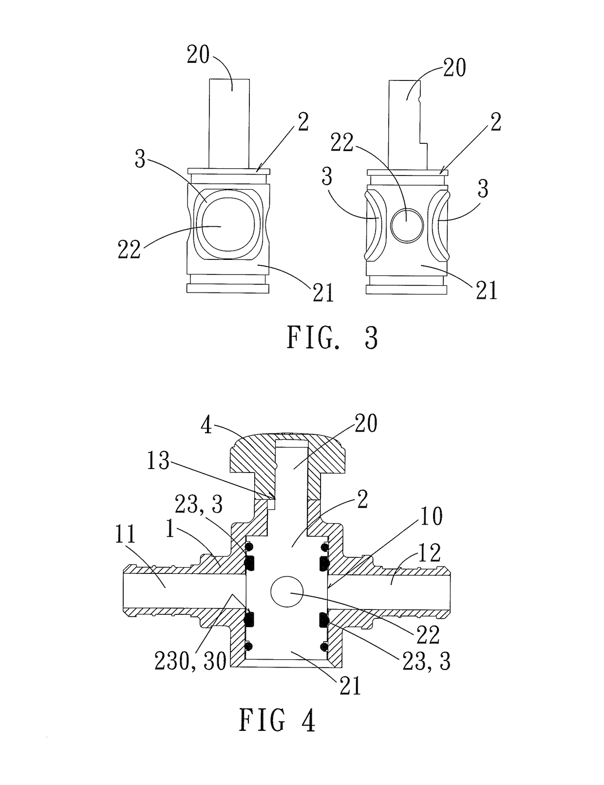
[0015]Referring to the drawings and initially to FIGS. 2-4, a stop valve in accordance with the preferred embodiment of the present invention comprises a valve body 1 having an interior provided with a receiving space 10, a shaft 2 rotatably mounted in the receiving space 10 of the valve body 1, and an operation member 4 mounted on the shaft 2.

[0016]The valve body 1 has a first side provided with a first channel 11 connected to the receiving space 10 to allow input of a fluid and a second side provided with a second channel 12 connected to the receiving space 10 to allow output of the fluid. The receiving space 10 of the valve body 1 is disposed between the first channel 11 and the second channel 12. The valve body 1 has a top provided with an opening 13.

[0017]The shaft 2 has a first end provided with a shaft body 21 disposed between the first channel 11 and the second channel 12 of the valve body 1 and a second end provided with a driven portion 20 protruding outward from the openi...


PUM


Abstract

A stop valve includes a valve body having a receiving space, a shaft rotatably mounted in the receiving space of the valve body, and an operation member mounted on the shaft. The shaft has a shaft body and a driven portion. The shaft body is provided with a connecting hole. The shaft body has a periphery provided with two retaining grooves for mounting two seal rings. The two seal rings are directly formed in the two retaining grooves of the shaft body in a secondary molding mode so that the two seal rings and the two retaining grooves of the shaft body have greater strength of combination, such that the two seal rings will not be detached from the two retaining grooves of the shaft body, thereby preventing from incurring fluid leakage.

Description

BACKGROUND OF THE INVENTION[0001]1. Field of the Invention[0002]The present invention relates to a valve and, more particularly, to a stop valve.[0003]2. Description of the Related Art[0004]A conventional stop valve in accordance with the prior art shown in FIG. 1 comprises a valve body “A” having an interior provided with a receiving space “B”, a shaft “C” rotatably mounted in the receiving space “B” of the valve body “A”, and an operation member “L” mounted on the shaft “C”. The valve body “A” has a first side provided with a first channel “D” connected to the receiving space “B” to allow input of a fluid and a second side provided with a second channel “E” connected to the receiving space “B” to allow output of the fluid. The receiving space “B” of the valve body “A” is disposed between the first channel “D” and the second channel “E”. The valve body “A” has a top provided with an opening “G”. The shaft “C” has a first end provided with a shaft body “H” disposed between the first...

Claims


Application Information

Patent Timeline
IPC IPC(8): F16K5/04
CPCF16K5/0478
Inventor SHU, HSIN-YUYEH, YEN-LING
Owner SOLEN ELECTRIC
Learn More