
Valve device

Active Publication Date: 2019-06-27
MIKUNI CORP
View PDF7 Cites 0 Cited by
  • Summary
  • Abstract
  • Description
  • Claims
  • Application Information

AI Technical Summary

Benefits of technology

This patent is for a valve device that has a simple structure and can prevent fluid from leaking during closure in a specific region without adding extra components.

Problems solved by technology

Therefore, it is not possible to provide the sheet part in ranges in which the valve shaft and the butterfly valve rotate.
In addition, although a covering part that is continuous with the sheet parts is provided to partially cover the circumference of the valve shaft, it is not possible to cover the entire circumference of the valve shaft.
Therefore, there is a concern that fluid leakage may occur from the upstream side toward the downstream side in the region where the sheet parts and the covering part are not present.
Therefore, in order for the butterfly valve to be able to rotate to a closing position, it is not possible to provide the stepped surface such that an outer edge (diameter part) of the butterfly valve does not interfere with the stepped surface in a region in the vicinity of the valve shaft in which the butterfly valve is turned.
Therefore, there is a concern that fluid leakage may occur from the upstream side toward the downstream side in the region where the stepped surface is not present.

Method used


Image

  • Valve device
  • Valve device
  • Valve device

Examples


Embodiment Construction

[0044]Hereinafter, an embodiment of the present invention will be described with reference to the accompanying drawings.

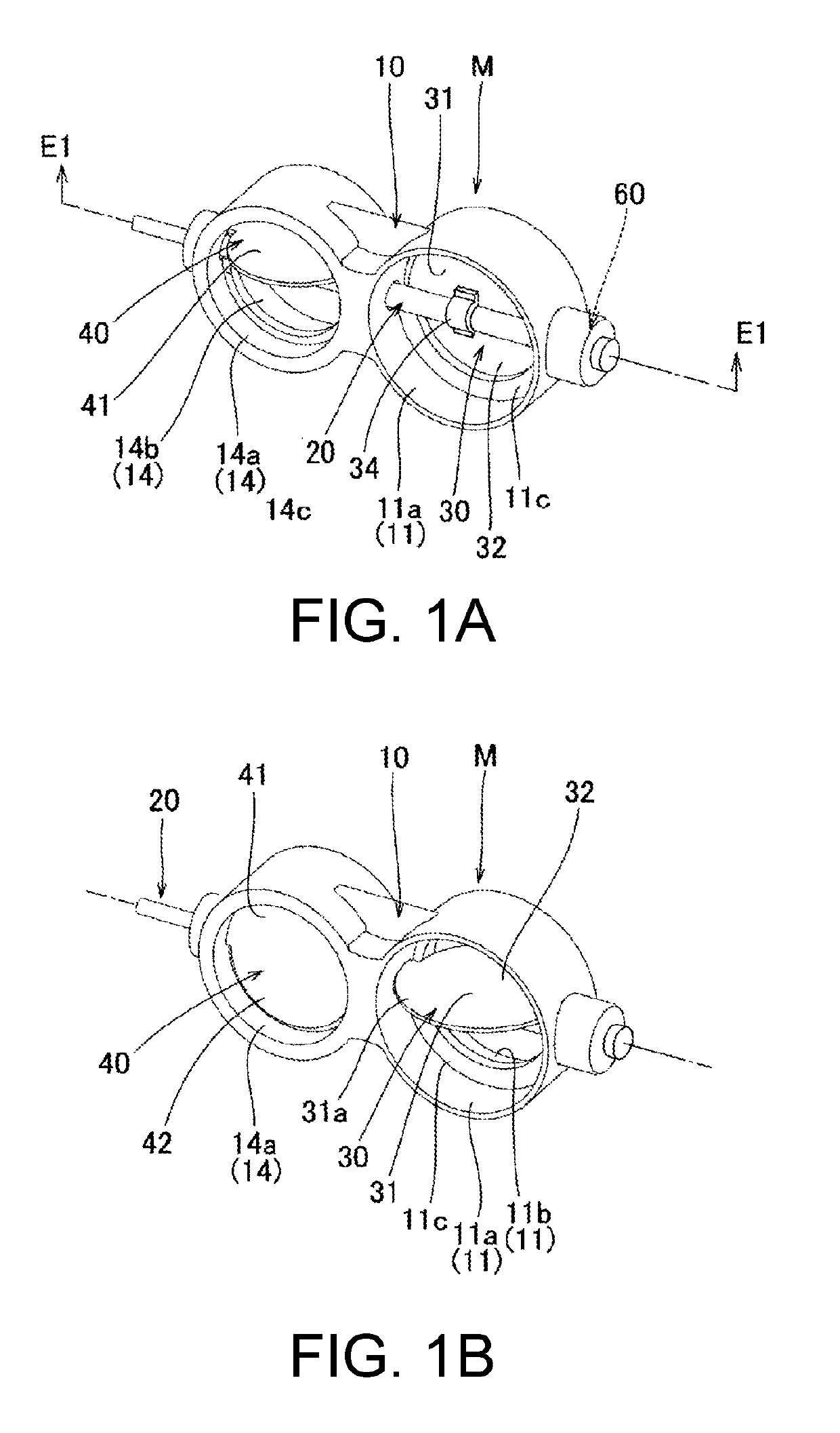
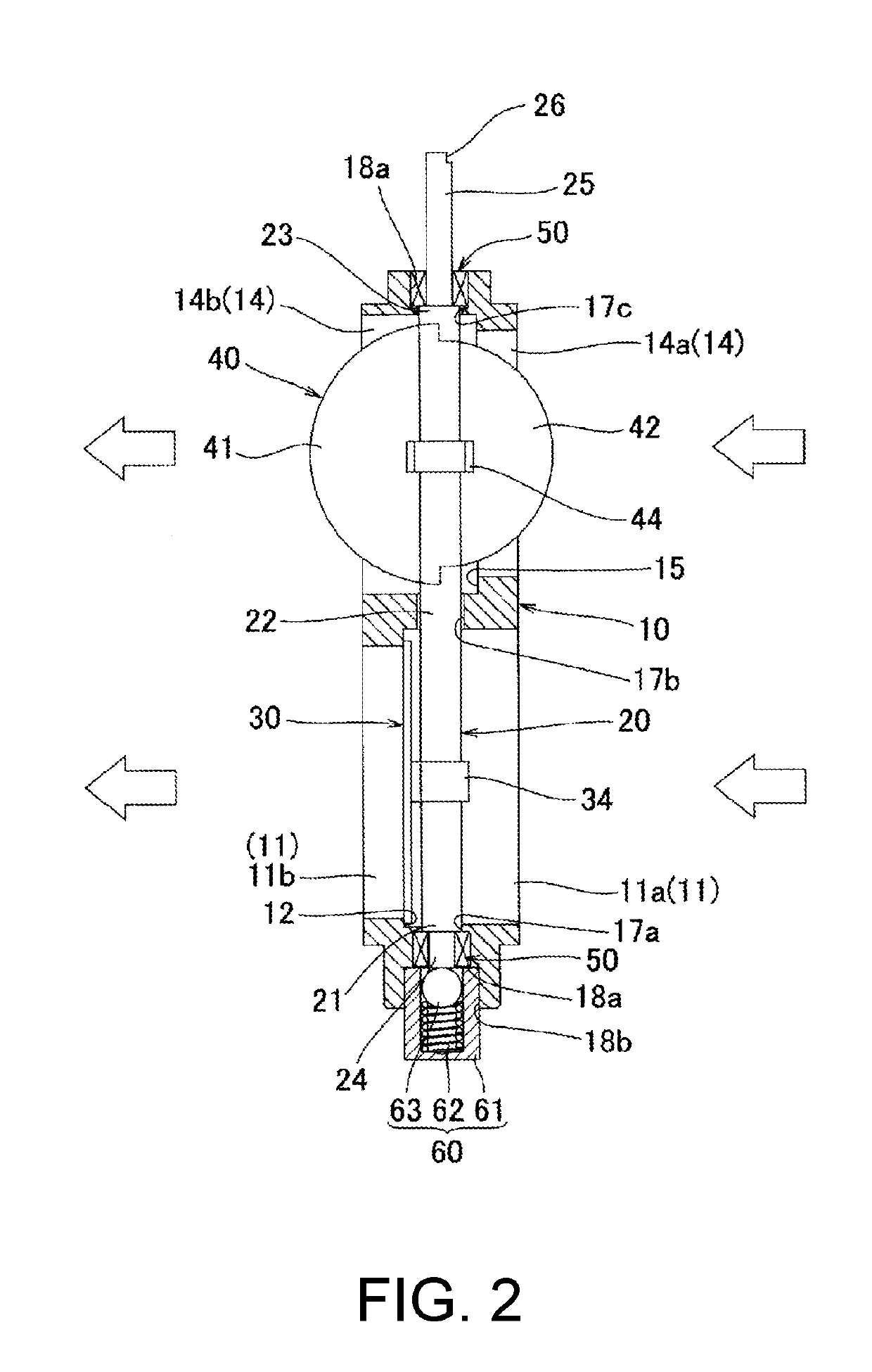
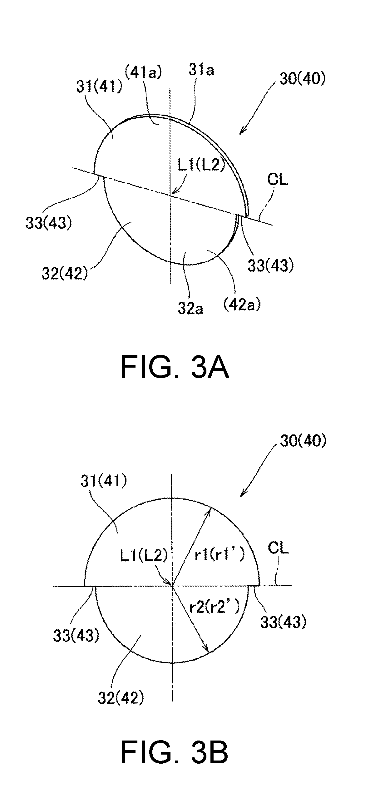
[0045]A valve device M according to the embodiment includes a body 10, a valve shaft 20, a main butterfly valve 30 and a sub butterfly valve 40 as butterfly valves, two bearings 50, and a biasing member 60 (a cylindrical holder61, a spring 62, a ball 63) as illustrated in FIGS. 1 to 7B.

[0046]The body 10 includes a main passage 11 that serves as a passage for causing a fluid to pass therethrough, a first seal part 12 and a second seal part 13 that are formed in the main passage 11, a sub passage 14 that serves as a passage for causing the fluid to pass therethrough, a first seal part 15 and a second seal part 16 that are formed in the sub passage 14, valve shaft holes 17a, 17b, and 17c through which the valve shaft 20 is caused to pass, two fitting holes 18a to which bearings 50 are attached, an attachment recessed part 18b to which a biasing member 60 is attached, ...


PUM


Abstract

This valve device includes a body having passages and valve shaft holes, a valve shaft passed through the valve shaft holes in a rotatable manner, and butterfly valves. The butterfly valves include first contour parts and second contour parts forming outer contour parts that are smaller than the first contour parts. The first and second contour parts are fixed to the valve shaft in order to close off the passages at positions set apart from the valve shaft holes toward the downstream side (upstream side) of the passages, and are disposed flanking a straight line parallel to the valve shaft to form prescribed outer contour parts. The body includes first seal parts with which the first contour parts are brought into contact and second seal parts with which the second contour parts are brought into contact within the passages. Fluid leakage in a closed state can thereby be reliably prevented.

Description

TECHNICAL FIELD[0001]The present invention relates to a valve device that includes butterfly valves that open and close passages for causing a fluid to pass therethrough, and for example, a valve device that is applied to opening and closing of passages that causes a fluid at a high temperature to pass therethrough, such as an exhaust system for an engine.BACKGROUND ART[0002]As a conventional valve device, a valve device that includes a housing that has a fluid passage, a valve shaft that is held by the housing in a rotatable manner, a butterfly valve with a circular plate shape that is secured to the valve shaft and opens and closes the fluid passage, and two semicircular-arc-shaped sheet parts that are formed to protrude from an inner surface of the fluid passage such that the butterfly valve is brought into contact with the semicircular-arc-shaped sheet parts dining closure, and the like is known (see Patent Literature 1, for example).[0003]In this valve device, contact surfaces ...

Claims


Application Information

Patent Timeline
IPC IPC(8): F02D9/10F02D9/04F16K3/08F16K3/10
CPCF02D9/1095F02D9/101F02D9/04F02D9/106F16K3/08F16K3/10F01N5/02F02D9/10F16K1/22F16K1/226Y02T10/12F02M26/70F02D9/1045F16K27/0218F16K1/222
Inventor ISHII, TOSHIAKI
Owner MIKUNI CORP
Learn More