Display control device for vehicle

a control device and vehicle technology, applied in the direction of electric control, speed sensing governors, instruments, etc., can solve the problems of reducing the driving force, the driver cannot feel the use of engine performance to the limit, and the shock is given to the vehicle, so as to suppress the incongruity. , the effect of reducing the smoothing amoun

Active Publication Date: 2017-09-21
TOYOTA JIDOSHA KK
View PDF4 Cites 3 Cited by
  • Summary
  • Abstract
  • Description
  • Claims
  • Application Information

AI Technical Summary

Benefits of technology

[0012]According to the vehicle display control device as described above, as the vehicle acceleration or the engine rotational speed gradient is larger in smoothing, the smoothing amount becomes smaller. Accordingly, as the vehicle acceleration or the engine rotational speed gradient is larger, change in the display rotational speed becomes larger. Therefore, it becomes possible to suppress the sense of incongruity imparted to the driver due to mild change in the display rotational speed even though the vehicle acceleration or the engine rotational speed gradient is large.

Problems solved by technology

As a result, driving force decreases and shocks are given to the vehicle.
Therefore, the driver cannot feel the use of engine performance to the limit.

Method used


Image

  • Display control device for vehicle
  • Display control device for vehicle
  • Display control device for vehicle

Examples


Embodiment Construction

[0020]Hereinbelow, an embodiment of the present disclosure will be described in detail with reference to the accompanying drawings. In the following embodiment, the drawings are simplified or deformed as necessary, and therefore the details of each component, such as a proportion, and a form, may be different from those of real components.

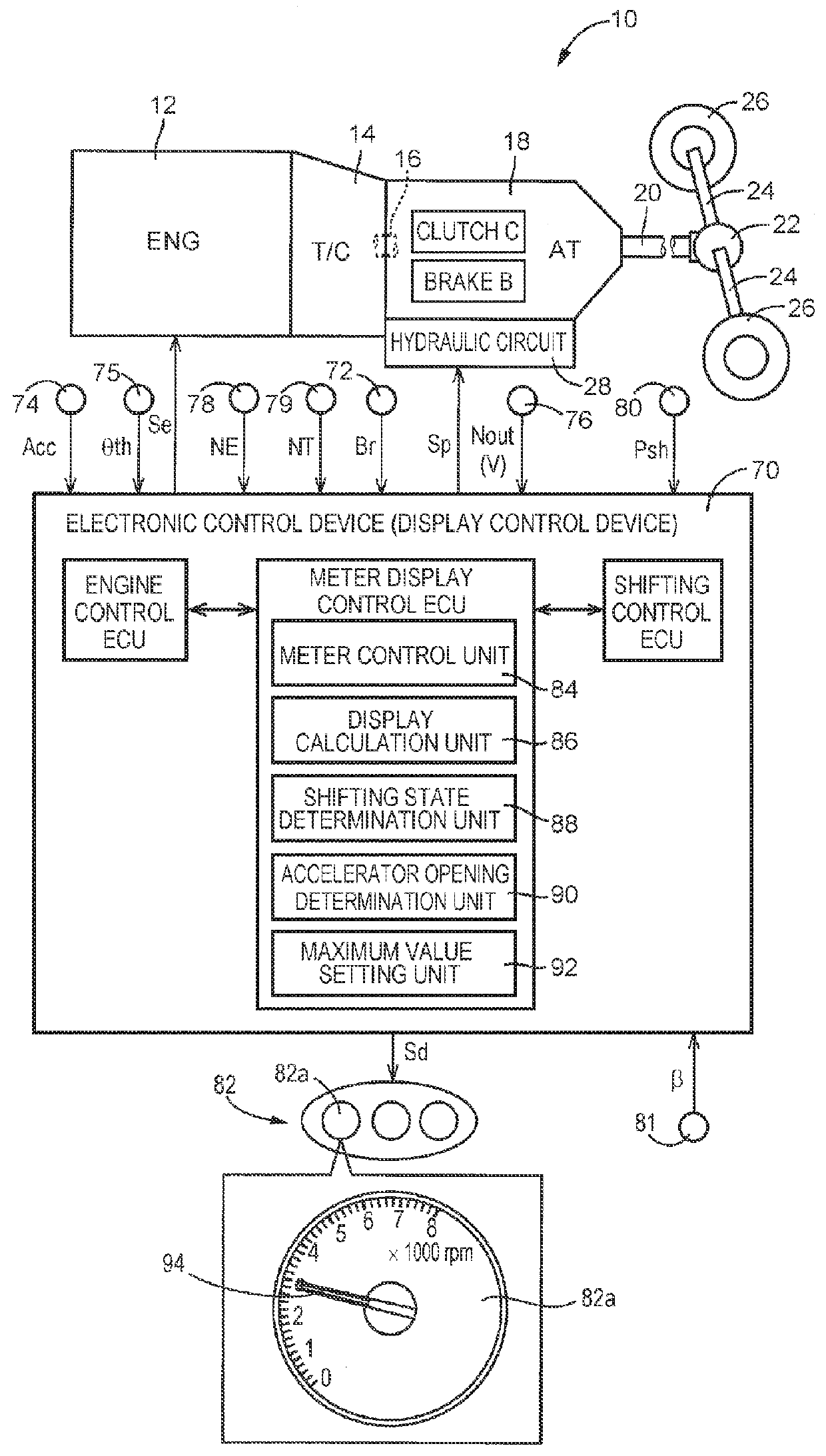
[0021]FIG. 1 is an explanatory view of an outlined configuration of a power transmission line extending from an engine 12 to driving wheels 26 included in a vehicle 10 to which a display control device of the present embodiment is applied, the view being also an explanatory view of a principal part of a control system provided in the vehicle 10. In FIG. 1, motive power generated in the engine 12 serving as a driving force source passes through a torque converter 14 and an input shaft 16, and is input into an automatic transmission 18 from the input shaft 16. The motive power is then transferred from an output shaft 20 of the automatic transmission ...


PUM


Abstract

A target reaching rotational speed set during a torque phase is set to a value higher than an actual engine rotational speed, the value being higher as one of a vehicle acceleration and an engine rotational speed gradient is larger. That is, as the acceleration is steeper, the target reaching rotational speed is set to a value closer to an upper limit rotational speed or rotational speeds proximate thereto. Thus, a display rotational speed displayed on a tachometer at the end of the torque phase becomes high rotational speed. Accordingly, there is provided a display control device for a vehicle that enables a driver to feel the use of engine performance to the limit.

Description

CROSS-REFERENCE TO RELATED APPLICATIONS[0001]This application claims priority to Japanese Patent Application No. 2016-056175 filed on Mar. 18, 2016, the entire contents of which are hereby incorporated by reference.BACKGROUND1. Technical Field[0002]The present disclosure relates to a display control device for a vehicle, and more particularly relates to display of a meter during an upshift.2. Description of Related Art[0003]There has been known a display control device provided in a vehicle including an engine and an automatic transmission, the device being configured to display engine rotational speed on a meter. The engine rotational speed display device is disclosed in Japanese Patent Application Publication No. 2009-220678. In the engine rotational speed display device disclosed in Japanese Patent Application Publication No. 2009-220678, responsiveness of engine rotational speed for display (meter-displayed rotational speed) corresponding to change in actual engine rotational sp...

Claims


Application Information

Patent Timeline
Patent Type & Authority Applications(United States)
IPC IPC(8): G01M15/04
CPCG01M15/046B60K35/00B60K37/02F02D41/023G01P1/08G01P1/10F02D31/009B60W50/14B60W2050/146B60W2510/0638B60K2370/154F16H59/00B60W30/19F16H61/36
Inventor TERATANI, YOSHIYUKI
Owner TOYOTA JIDOSHA KK
Why Eureka
Try Eureka