Pneumatic tire and method for manufacturing pneumatic tire

Active Publication Date: 2017-09-28
SUMITOMO RUBBER IND LTD
View PDF3 Cites 3 Cited by
  • Summary
  • Abstract
  • Description
  • Claims
  • Application Information

AI Technical Summary

Benefits of technology

[0019]The band of the tire according to the present invention includes the center portion located in the axial center. The center portion has the helically wound structure in which the first band body including the first cord is wound in the circumferential direction. During high-speed traveling, a radial outside of the center portion mainly contacts the ground. Binding force of the first band body extending in the circumferential direction is strong. Accordingly, deformation of the tread caused by centrifugal force during high-speed traveling is suppressed. Furthermore, since the first band body extends in the circumferential direction, torsional rigidity in the vicinity of the center of the tread is suppressed. The tire including the band suppresses kickback from occurring during high-speed traveling. The tire is excellent in high speed stability.
[0020]The band includes the shoulder portion located on the axial outside of the center portion. The shoulder portion has the meshed structure formed by the second band body inclu

Problems solved by technology

On the other hand, owing to the large cornering power, kickback is likely to be caused by an external disturbance input during high-speed traveling.
The tire includi

Method used


Image

  • Pneumatic tire and method for manufacturing pneumatic tire
  • Pneumatic tire and method for manufacturing pneumatic tire
  • Pneumatic tire and method for manufacturing pneumatic tire

Examples


example 1

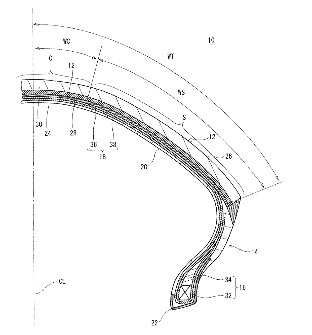
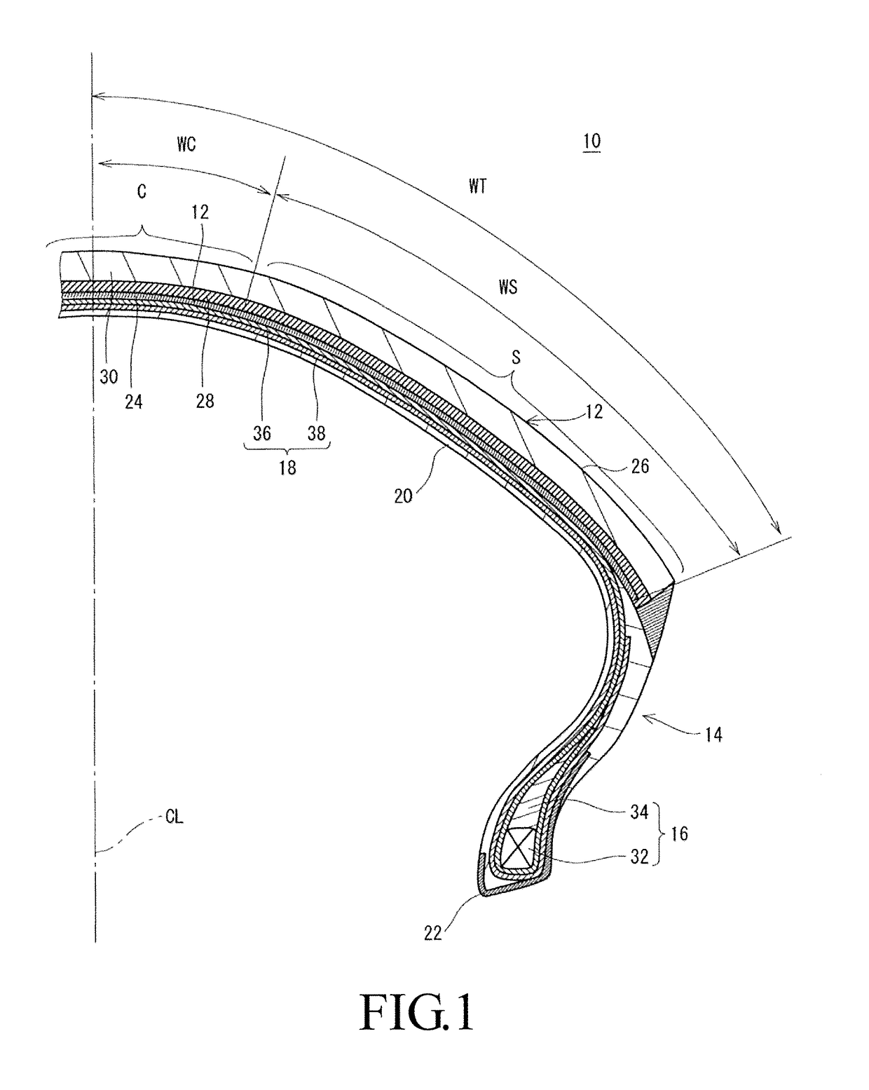
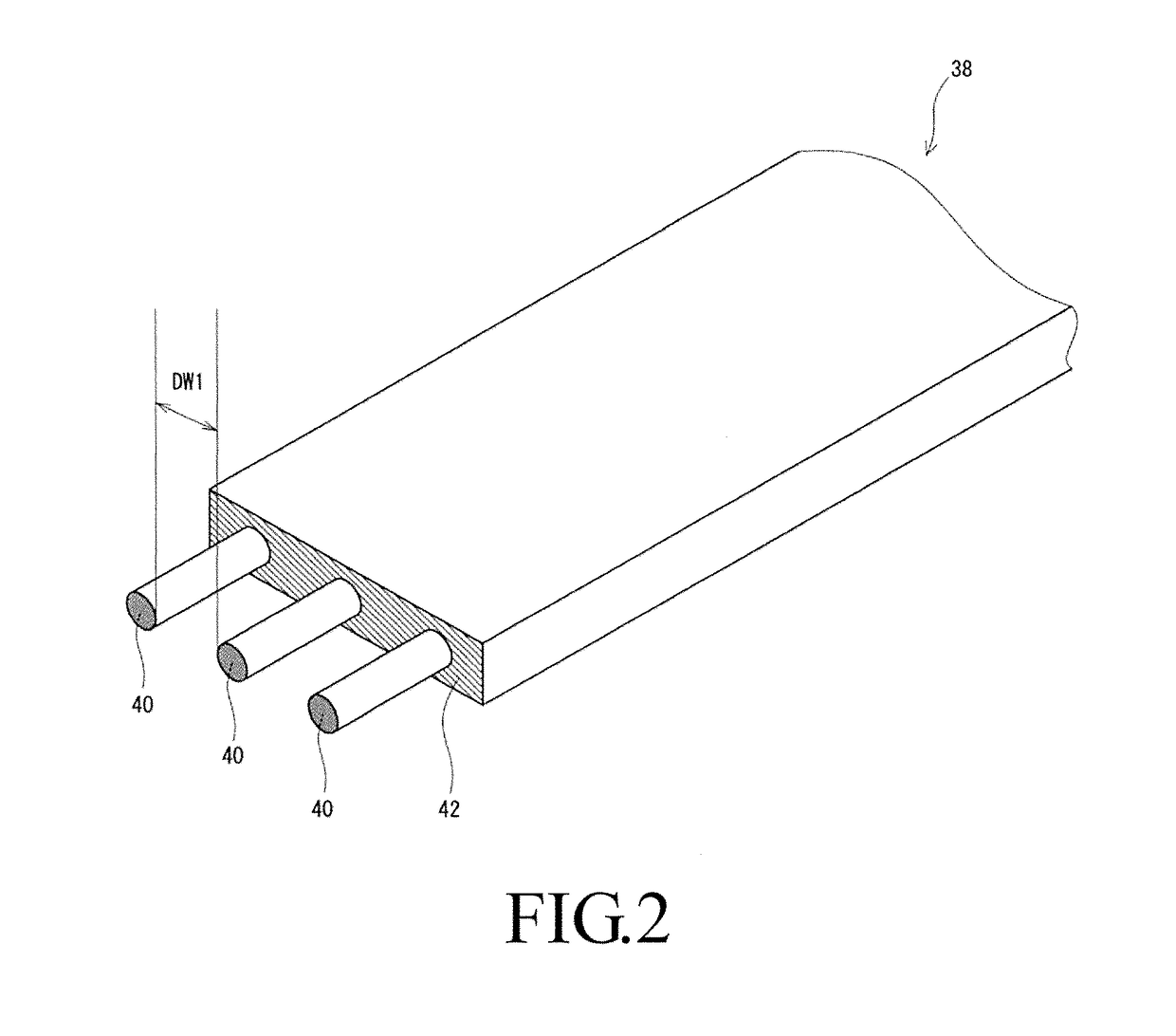
[0093]A pneumatic tire having the structure shown n FIG. 1 was manufactured. The size of this tire is “120 / 70ZR17.” A band of this tire has the structure shown in FIG. 3. This is shown as “FIG. 3” in the column “Band structure” in Table 1. In this tire, the third portions are arranged in the circumferential direction with no gap and no overlap therebetween. The absolute value of the inclination angle θ1 was set to be the same as the absolute value of the inclination angle θ2. In this tire, a common band body is wound to form the center portion C and the shoulder portion S. That is, the first band body is the same as the second band body. The number of cords of this band body is three, and a distance between the cords is 1 mm.

examples 6-8

[0098]Tires of Examples 6 to 8 were obtained in the same manner as in Example 1 except that the quantity of the cords of the band was decreased to change the band cost to the values shown in Table 3. Moreover, the band cost is expressed by an index based on the cost of the band of the tire of Comparative Example 1 as 100.

[0099][Cornering Power]

[0100]The cornering power (CP) was measured using a flat belt tire tester under the following measurement conditions.

[0101]Rim used: MT3.50×17

[0102]Internal pressure: 250 kPa

[0103]Load: 1.3 kN

[0104]Speed: 30 km / h

[0105]Camber angle: 0°

[0106]Slip angle: 1°

[0107]The results were indexes based on the value of Comparative Example 1 being set as 100 and were shown in the following Tables 1 to 3. The greater the value, the larger the cornering power.

[0108][Response, Turning Ability, Stability During Bank, and Kickback Resistance]

[0109]A trial tire was incorporated into a standard rim (size=MT3.50×17) and was mounted on a front wheel of a two-wheeled ...


PUM


Abstract

A pneumatic tire excellent in high speed stability and turning ability is provided. In a band of a tire, a center portion located in an axial center has a helically wound structure in which a first band body including a first cord is wound. A shoulder portion located on an axial outside of the center portion has a meshed structure formed by a second band body including a second cord. The shoulder portion includes a plurality of first portions, a plurality of second portions and a plurality of third portions. Each first portion is inclined and extends from an axially inner end of the shoulder portion to an axially outer end of the shoulder portion. Each second portion is inclined in an opposite direction from the first portion and extends from the axially inner end of the shoulder portion to the axially outer end of the shoulder portion.

Description

CROSS-REFERENCE TO RELATED APPLICATION[0001]This application claims the priority benefit of Japan Application no. 2016-063585, filed on Mar. 28, 2016. The entirety of the above-mentioned patent application is hereby incorporated by reference herein and made a part of this specification.BACKGROUND OF THE INVENTION[0002]Field of the Invention[0003]The present invention relates to a pneumatic tire.[0004]Description of the Related Art[0005]A tire for two-wheeled vehicles may include a belt for reinforcing a carcass. Generally, the belt has a two-cut structure. On the belt, a plurality of cords inclined with respect to a circumferential direction and a plurality of cords inclined in an opposite direction from the aforementioned plurality of cords with respect to the circumferential direction are superimposed. An absolute value of an inclination angle of the cords typically ranges from 17° to 24°. The belt contributes to torsional rigidity of the tire. This tire has a large cornering powe...

Claims


Application Information

Patent Timeline
IPC IPC(8): B60C9/20B29D30/30
CPCB60C9/20B60C2200/10B60C2009/2012B29D30/30B60C9/18B60C9/2204B60C9/263B60C2009/2035B29D30/1635B29D30/3035B29D30/70B60C2009/2016B60C2011/0091B60C2009/2025
Inventor ICHIRYU, YUTAKA
Owner SUMITOMO RUBBER IND LTD
Why Eureka
Try Eureka