Sleeping position-controlling bed system

a technology of position control and bed, which is applied in the field of bed system, can solve the problems of bedridden patients and elderly people who are often unable to change their posture in bed by themselves, are likely to have blood circulation disorders, and chronic sleep deprivation, so as to prevent bedridden people, eliminate or reduce their parasomnia, and improve the quality of sleep of peopl

Active Publication Date: 2017-10-05
TIZAI KEIEISHA
View PDF0 Cites 2 Cited by
  • Summary
  • Abstract
  • Description
  • Claims
  • Application Information

AI Technical Summary

Benefits of technology

The present invention is a bed system that can automatically control a user's sleeping posture based on their body condition. The bed system can detect body movements or abnormal behaviors during sleep and adjust the bed accordingly to prevent pressure ulcers, apnea, and other sleep-related issues. The bed system also helps people with pain or heart problems sleep comfortably by keeping them in a low-load posture. Overall, the bed system improves the quality of sleep for people with various sleep disorders and promotes heart health.

Problems solved by technology

Patients and aged people who are bedridden often cannot change their posture in bed by themselves.
Therefore, they are likely to have blood circulation disorders at a contact area between the body and the surface of the bed that supports the body and then to suffer from pressure ulcers.
Meanwhile, those who suffer from sleep apnea syndrome causing the cessation of breathing or hypopnea, snoring, or teeth grinding are in a state of chronic sleep deprivation due to a continuous lack of quality sleep and may even die suddenly.
Furthermore, those who suffer from low-back pain and shoulder pain, and patients who have just undergone surgery are often unable to fall asleep unless they are in a comfortable posture.
Even if they get to sleep, they may involuntary change their posture during sleep and be woken up by a sudden pain.
Chronic sleep deprivation due to these causes may prevent affected people from having a healthy life, and possibly cause a catastrophic accident involving human lives.
Nevertheless, most of these people are unaware of having such sleep disorders themselves.

Method used


Image

  • Sleeping position-controlling bed system
  • Sleeping position-controlling bed system
  • Sleeping position-controlling bed system

Examples


first embodiment

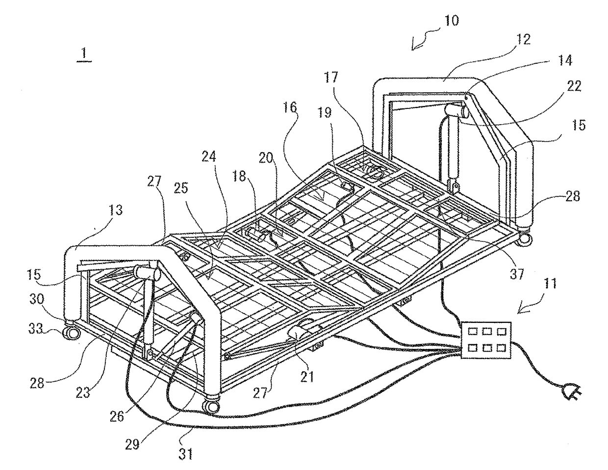
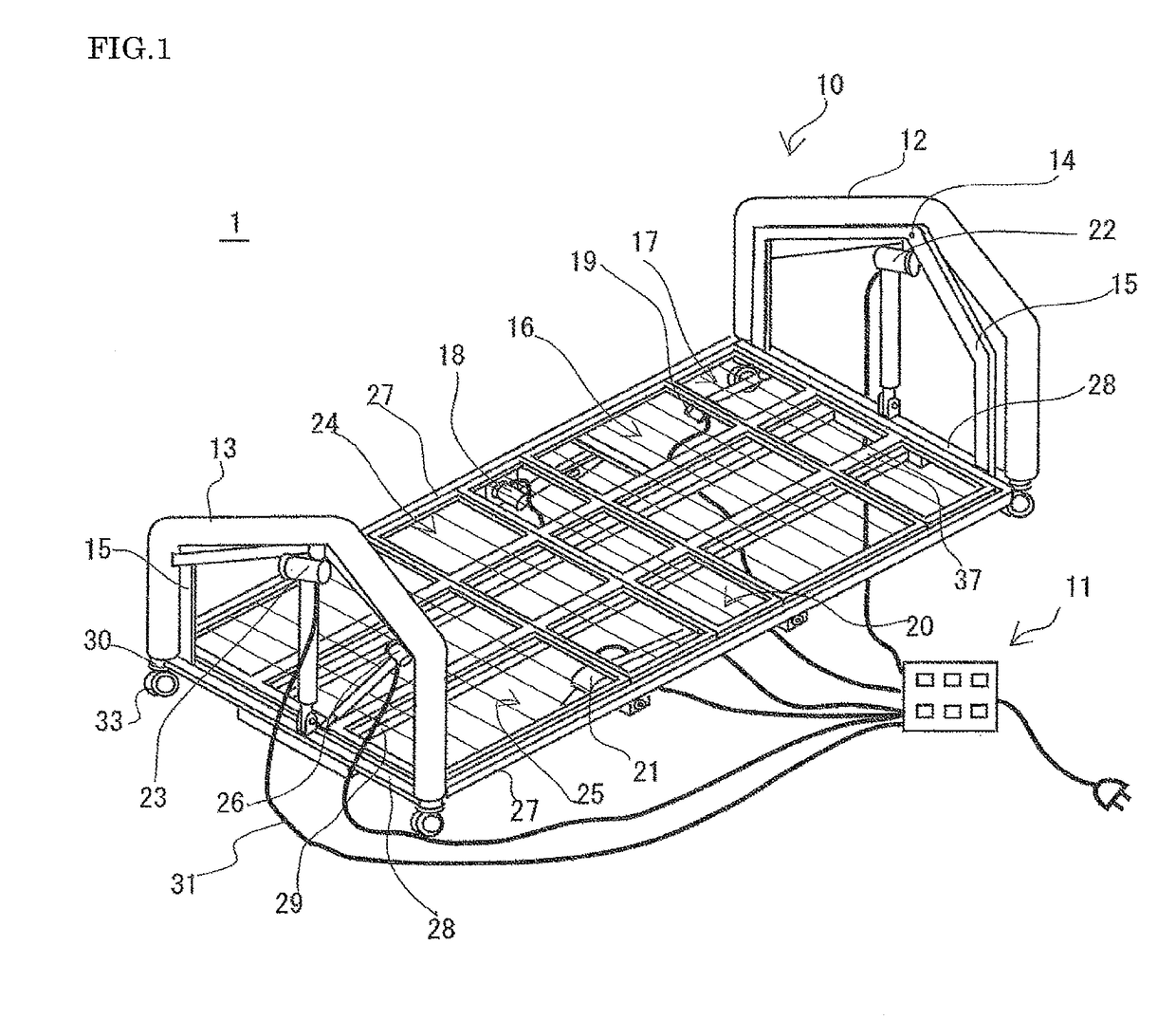
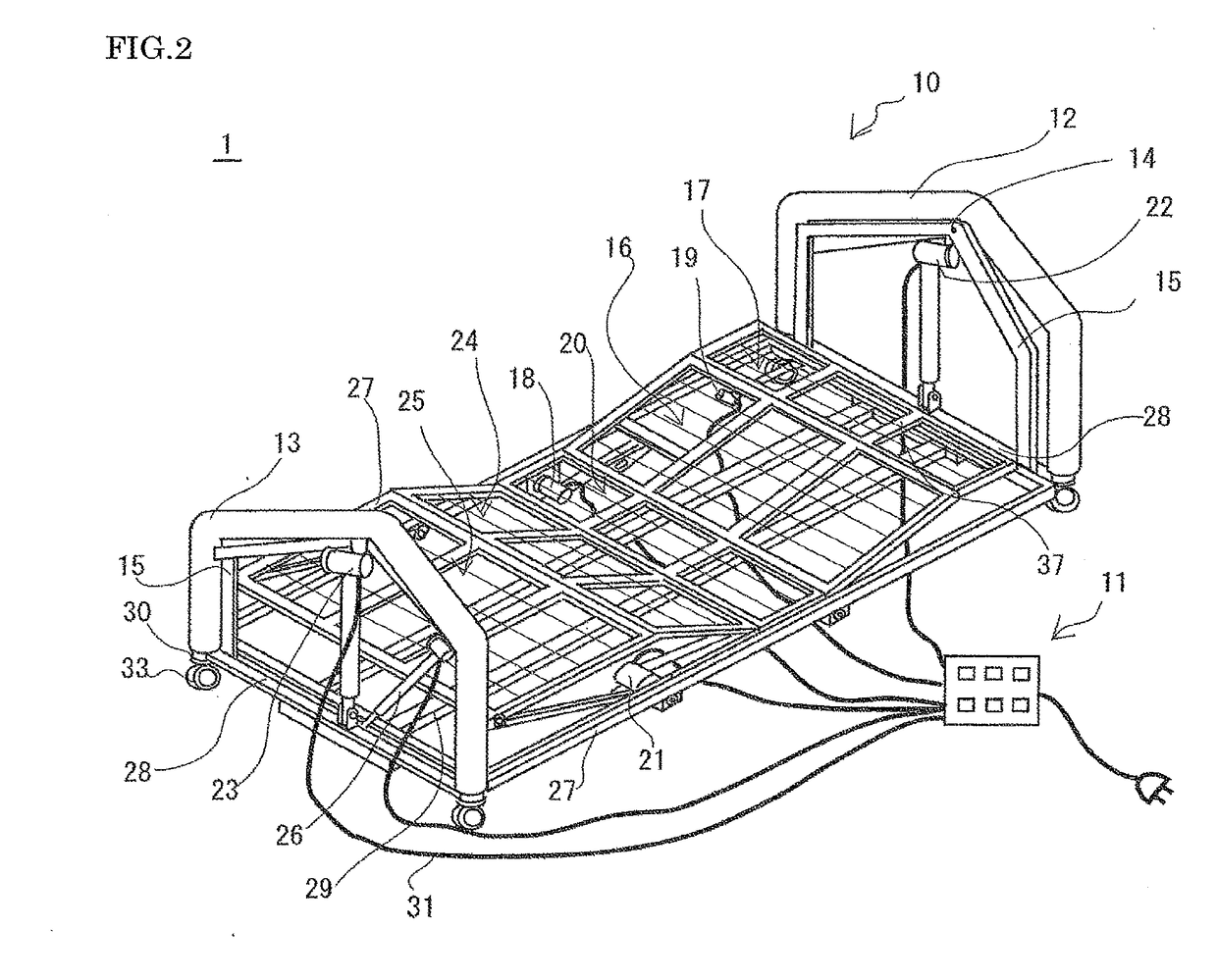
[0113]FIG. 1 shows a sleeping-posture-control bed system 1 of a first embodiment of the present invention, which includes a bed body 10 and an operating unit 11. The bed body 10 includes a bed floor on which the user lies, and a bed-floor support body which supports the bed floor. The bed floor mainly includes two lateral frame members 28, two longitudinal frame members 27 each connecting one end of each of the lateral frame members 28, and two connecting members 37 disposed between the longitudinal frame members 27 so as to connect the lateral frame members. This framework is suspended by two suspension members 15 fixed to reinforcing members 32 of a head frame 12 and a foot frame 13. The framework forms the upper surface of the bed floor, which is hereinafter also referred to as the “bottom surface” on or over which the user lies.

[0114]The bed floor includes a head-receiving surface portion 17, a back-receiving surface portion 16, a waist-receiving surface portion 20, an upper-leg...

second embodiment

[0177]FIG. 10 shows a bed body of a sleeping-posture-control bed system of a second embodiment of the present invention, and FIG. 11 shows its overall structure (block diagram). The bed system of the second embodiment includes a bed body 501 (see FIG. 10) having a suspended bed floor portion 102 with a bottom surface 120; a sleep monitor 502 for monitoring the sleep of the user sleeping on the bottom surface 120; a parasomnia detector 503 for determining the presence or absence of parasomnias from the monitoring data of the sleep monitor 502; a bed-floor tilt driver 505 for tilting the bed floor portion 102 having the bottom surface 120; a tilt driving controller 504 for controlling the bed-floor tilt driver 505 so that the bottom surface 120 can be tilted on the basis of the determination result of the parasomnia detector 503; and a barycentric position detector 506 for detecting the position of the user's center of gravity on the bottom surface (see FIG. 11). In the first embodime...

third embodiment

[0230]The present embodiment describes a bed system which allows both the tilting of head- and back-receiving surfaces and the lateral tilting of the bed floor. The present embodiment is identical to the first embodiment except that it is essential to control the lateral tilting of the bed floor. Therefore, the description of common aspects (such as the configuration of the bed body) will be omitted. FIG. 15 is a block diagram of the overall structure of the sleeping-posture-control bed system of the third embodiment.

[0231]The present embodiment has the same configuration as the first embodiment described with FIG. 6 except that it includes a bed-floor tilt driver 708 as an essential component. The bed-floor tilt driver 708 is a driver for tilting the bed floor of the bed body 701 in the lateral direction. The user can be induced to change his / her posture in bed by tilting the bed floor in the lateral direction. The bed-floor tilt driver 708 is composed, for example of the driver 26...


PUM


Abstract

The sleeping-posture-control bed system includes a bed floor including a back-lifting portion for lifting the user's back, a bed-floor support body supporting the bed floor, and a back-lifting driver for lifting the head side of the back-lifting portion. The back-lifting portion includes a back-receiving surface and a head-receiving surface tiltable at different angles. The back-lifting driver lifts the back-receiving surface and the head-receiving surface, satisfying Mathematical Formula (1):0°<θx≦70°,−45°≦θy<0°, and −30°≦θx+θy  (1)where θx is the tilt angle of the back-receiving surface when tilted, and the tilt angle of the back-receiving surface when the back-receiving surface is not lifted is set to be 0°; and θy is the tilt angle of the head-receiving surface when the angle of an extended line of the back-receiving surfaceat the tilt angle θx is referred to as 0°.

Description

CROSS REFERENCE TO RELATED APPLICATION[0001]The present invention is a Divisional application of U.S. patent application Ser. No. 14 / 405,047, filed on Dec. 2, 2014, which is a National Stage Application filed under 35 USC '371 of International Application No. PCT / JP2013 / 072124, filed Aug. 19, 2013, and which is based upon and claims the benefit of priority from the subject matter related to Japanese Patent Application No. 2012-181260 filed on Aug. 18, 2012, and Japanese Patent Application No. 2012-234214 filed on Oct. 23, 2012 in the Japan Patent Office, the entire contents of which are hereby incorporated by reference.TECHNICAL FIELD[0002]The present invention relates to a bed system controlling a user's sleeping posture.BACKGROUND ART[0003]Many bedridden patients cannot turn over in bed and have blood circulation disorders with the risk of developing pressure ulcers (also called “bed sores”). Pressure ulcers deteriorate the health status of patients sometimes crucially. To avoid t...

Claims


Application Information

Patent Timeline
Patent Type & Authority Applications(United States)
IPC IPC(8): A61G7/018A61G7/00G06K9/00A61G7/008A61B5/00A61B5/11A61G7/015A61G7/005
CPCA61G7/018A61G7/015A61G7/001A61G7/005A61G2203/30A61B5/4806A61B5/1114G06K9/00369A61G7/008A61B5/1116A61G7/002A61G7/05A61G7/057A61G2203/70A61G2203/34A61G7/0573G06V40/103G06V40/161
Inventor MIYASHITA, TOSHIKOOHMAE, KANAME
Owner TIZAI KEIEISHA
Why Eureka
Try Eureka