Optical fiber cable and method for installing optical fiber cable

Inactive Publication Date: 2017-10-19
FURUKAWA ELECTRIC CO LTD
View PDF5 Cites 0 Cited by
  • Summary
  • Abstract
  • Description
  • Claims
  • Application Information

AI Technical Summary

Benefits of technology

The patent text describes a new type of optical fiber cable that is aesthetically pleasing and easy to install. This cable has a high light transmission rate, which means it lets light pass through without losing any quality. This makes it useful for transmitting large amounts of information without causing any visual interference. The text also mentions that this cable can be designed to look like a traditional copper cable, which makes it easier to install in places where it is needed. Overall, the patent describes a new technology that allows for better-looking and easy-to-install optical fiber cables.

Problems solved by technology

However, when the indoor cable is installed indoors, the indoor cable tends to stand out, thereby spoiling the overall appearance of the interior.
Thus, since the optical fiber core is composed of a transparent member, a transparent glass wire and a resin cover, the optical fiber core becomes inconspicuous.
However, since the entire optical fiber core is transparent, visibility during the process may become poor.
On the other hand, when the size of the outer sheath is 1.6 mm×2.0 mm, the outer diameter of the optical fiber core covered by the transparent member becomes larger than that of conventional optical fibers, and the arrangement of the tension member becomes difficult.

Method used


Image

  • Optical fiber cable and method for installing optical fiber cable
  • Optical fiber cable and method for installing optical fiber cable
  • Optical fiber cable and method for installing optical fiber cable

Examples


second embodiment

[0050]Next, a second embodiment will be described. FIG. 3 is a scheme that shows the optical fiber cable 1a. Note that in the following description, components that show the same functions as those described for optical fiber cable 1 are referred to with the same notations and redundant descriptions will be abbreviated.

[0051]Optical fiber cable 1a has substantially the same composition as optical fiber cable 1, but differs in that it has a supporting wire 21. In the cable part in which the optical fiber core 3 is arranged, a supporting wire part is coupled. The supporting wire part has a supporting wire 21. The supporting wire 21 is for supporting the optical fiber cable 1a when installing the optical fiber cable 1a. As the supporting wire 21, for example, galvanized steel wire may be utilized That is, the optical fiber cable 1a is used as a drop cable.

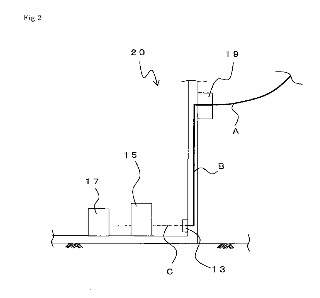
[0052]Next, the method of installing optical fiber cable using optical fiber cable 1a will be described. In FIG. 2, from outdoors to...

third embodiment

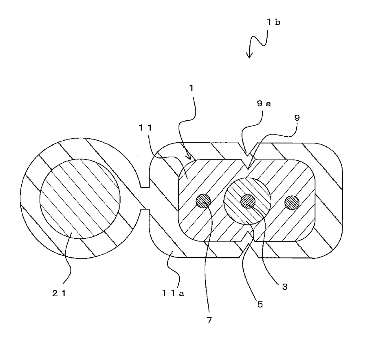
[0054]Next, a third embodiment will be described. FIG. 4 is a scheme of the optical fiber cable 1b. Optical fiber cable 1b has substantially the same composition as optical fiber cable 1a, but differs in that it incorporates an indoor cable.

[0055]On the side of the aforementioned optical fiber cable 1 (indoor cable) is arranged a supporting wire 21. In this state, an outer sheath 11a (second outer sheath) is provided in a way that covers outer sheath 11 (first outer sheath) of the optical fiber cable 1 and the supporting wire 21. That is, a drop cable is composed of outer sheath 11a.

[0056]On the outer periphery of the outer sheath 11a, notches 9a are formed at positions facing each other. By rupturing the outer sheath 11a from the top and bottom notches 9a using a cable splitter or the like, the optical fiber cable 1 inside can be separated from the supporting wire 21 and the outer sheath 11a and extracted. That is, outer sheath 11 and outer sheath 11a are not adhered or adhered wi...

fourth embodiment

[0059]Next, a fourth embodiment will be described. FIG. 5 is a scheme that shows optical fiber cable 1c. The optical fiber cable 1c has substantially the same composition as optical fiber cable 1, but differs in the shape of the tension members 7.

[0060]In optical fiber cable 1c, the shape of the cross section vertical to the longitudinal direction of the tension members 7 are substantially rectangular. As described previously, because it is necessary to enlarge the outer diameter of the optical fiber core 3 by the transparent member 5, when applying to small-sized indoor cables and so forth, the tension members 7 must be down-sized. In contrast, when the cross-sectional area of the tension members 7 become small, materials with higher strength must be selected.

[0061]In the present embodiment, the tension members 7 are to have substantially rectangular cross-sectional shapes and are positioned so that the short sides face the top and bottom direction. That is, the tension members 7 a...


PUM


Abstract

An optical fiber cable is composed of an optical fiber core, a tension member, an outer sheath, and so forth. The optical fiber core includes a glass wire and a resin-coated part, which is further coated by a transparent member on its outer periphery. The transparent member is, for example, urethane acrylate, PVC, nylon, and so forth. The transparent member preferably has a total light transmittance, defined by JIS K7361-1, of 60% or higher. The reason is that when the total light transmittance is less than 60%, the color tone of the optical fiber core (transparent member) becomes intense and stands out. Additionally, it is preferable that the total light transmittance of the transparent member is 80% or more.

Description

TECHNICAL FIELD[0001]The present disclosure relates to an optical fiber cable and so forth that is inconspicuous when installed indoors.BACKGROUND ART[0002]Usually, when optical fiber cable is drawn indoors, an indoor cable is used. The indoor cable is connected to the optical line termination device and connected to various fiber-optic utilizing equipment by LAN cables and so forth.[0003]As such optical fiber cable, for example, an optical fiber cable comprising tension members, an optical fiber core arranged between the tension members, and an outer sheath that wraps these together, with one or more cable sheath notch arranged along the periphery of the outer sheath in the longitudinal direction, is known (e.g., JP2008-A-65038).[0004]However, when the indoor cable is installed indoors, the indoor cable tends to stand out, thereby spoiling the overall appearance of the interior. Further, when using an optical cord and so forth to install indoor, it was necessary to connect such opt...

Claims


Application Information

Patent Timeline
IPC IPC(8): G02B6/44G02B6/46
CPCG02B6/4432G02B6/46G02B6/4415G02B6/44G02B6/4433G02B6/4431G02B6/02395G02B6/4401
Inventor TSUKAMOTO, MASAYOSHIHOSHINO, YUTAKA
Owner FURUKAWA ELECTRIC CO LTD
Why Eureka
Try Eureka