Inkjet printhead with air cavities defined by ribs protruding into fluid channel
- Summary
- Abstract
- Description
- Claims
- Application Information
AI Technical Summary
Benefits of technology
Problems solved by technology
Method used
Image
Examples
first embodiment
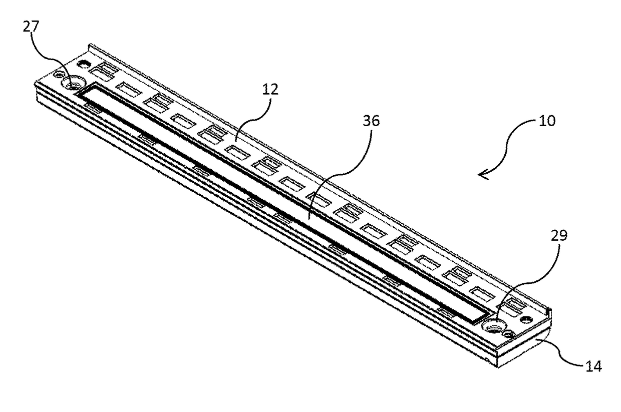
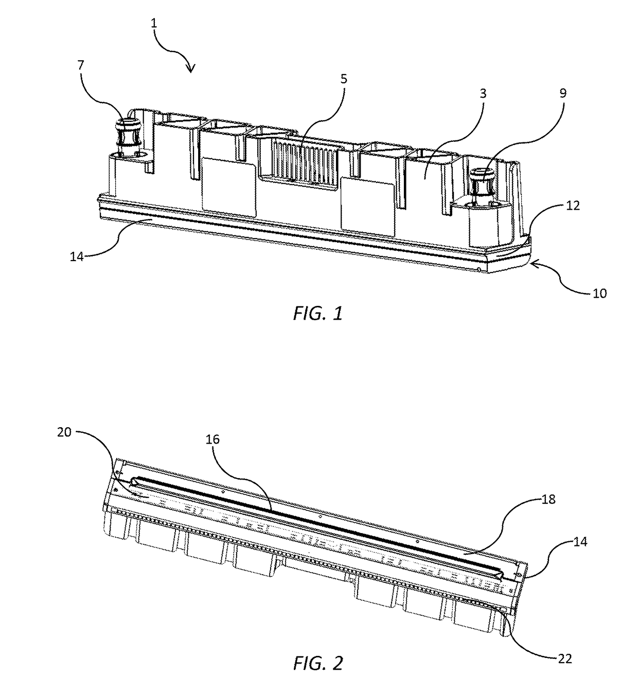
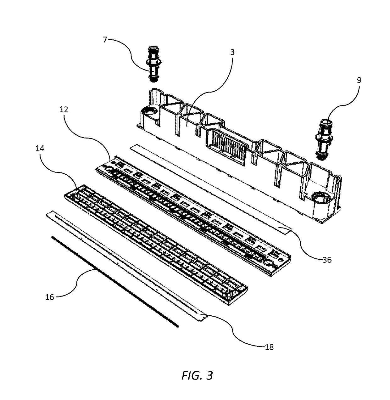
[0150]Referring now to FIGS. 10 to 16, in a first embodiment a base 41 of the lower ink manifold 14 comprises a floor 42 of the main ink channel 25, with the floor 42 defining a plurality of ink supply slots 44. The ink supply slots 44 receive ink from the main ink channel 25 and supply the ink into the backsides of the printhead chips 16 via the die-attach film 18. The ink supply slots 44 are longitudinally spaced apart along a length of the floor 42 and separated from each other by support webs, which take the form of diagonal joint webs 46 and transverse webs 48. The printhead chips 16 are attached to the base 41 of the lower ink manifold 14 via the adhesive die-attach film 18. The die-attach film 18 has a plurality of slot openings 50 mirroring the ink supply slots 44; and a plurality of film webs 52 mirroring the diagonal joint webs 46 and transverse webs 48 of the lower ink manifold 14.
[0151]The arrangement of the main ink channel 25 and ink supply slots 44 is designed to maxi...
second embodiment
[0154]Referring to FIGS. 17 to 22, in the lower ink manifold 14, the base 41 has a truss structure 60 supporting the printhead chips 16. The truss structure 60 has a first chord 62 and an opposite second chord 64, with a plurality of truss webs 66 extending between the two chords to define laterally flared ink outlets 61. The truss webs 66 are contiguously defined by a generally wavelike structure, which extends between the first and second chords 62 and 64 along the length of each printhead chip. Other truss configurations (e.g. regular diagonal webs) are, of course, within the ambit of the present invention.
[0155]The truss structure 60 provides excellent mechanical support for mounting the printhead chips 16. The truss webs 66 allow printhead chips 16 to be mounted to the base 41 of the lower ink manifold 14 with minimal chip cracking. Furthermore, the laterally flared ink outlets 61 are optimized for bubble venting as well as ink flow into the printhead chips.
[0156]As best shown ...
PUM
 Abstract
Description
Claims
Application Information
 - R&D
- Intellectual Property
- Life Sciences
- Materials
- Tech Scout
- Unparalleled Data Quality
- Higher Quality Content
- 60% Fewer Hallucinations
Browse by: Latest US Patents, China's latest patents, Technical Efficacy Thesaurus, Application Domain, Technology Topic, Popular Technical Reports.
© 2025 PatSnap. All rights reserved.Legal|Privacy policy|Modern Slavery Act Transparency Statement|Sitemap|About US| Contact US: help@patsnap.com


