Inkjet printhead with bubble-venting cavities offset from fluid outlets

a technology of fluid outlet and inkjet print head, which is applied in the direction of printing and inking apparatus, etc., can solve the problems of prone labyrinthine ink pathway, chip depriming, and limited practical limitations of lcp manifold, and achieve the effect of facilitating bubble venting

Active Publication Date: 2017-11-02
MEMJET TECH LTD
View PDF5 Cites 13 Cited by
  • Summary
  • Abstract
  • Description
  • Claims
  • Application Information

AI Technical Summary

Benefits of technology

The inkjet printhead described in the patent provides a stable structure for attaching a chip while still allowing for high ink flow rates and bubble venting. Additionally, the printhead facilitates bubble venting in a way that prevents bubbles from stagnating and blocking the ink flow pathways to the chip.

Problems solved by technology

However, at very high print speeds, the LCP manifold has some practical limitations.
Without a sufficient body of ink close to the printhead chips, the chips may become starved of ink under periods of high ink demand and lead to chip de-priming.
Secondly, the labyrinthine ink pathways are susceptible to trapping air bubbles; if an air bubble become trapped in the system, the printhead chips will become starved of ink and de-prime.
Thirdly, the air boxes provide a relatively stiff compliance in the hydrostatic system; if a particular group of nozzles demands higher ink flow, then the resistance of the air boxes may be too great to allow the hydrostatic system to respond dynamically to the increased demand.

Method used


Image

  • Inkjet printhead with bubble-venting cavities offset from fluid outlets
  • Inkjet printhead with bubble-venting cavities offset from fluid outlets
  • Inkjet printhead with bubble-venting cavities offset from fluid outlets

Examples


first embodiment

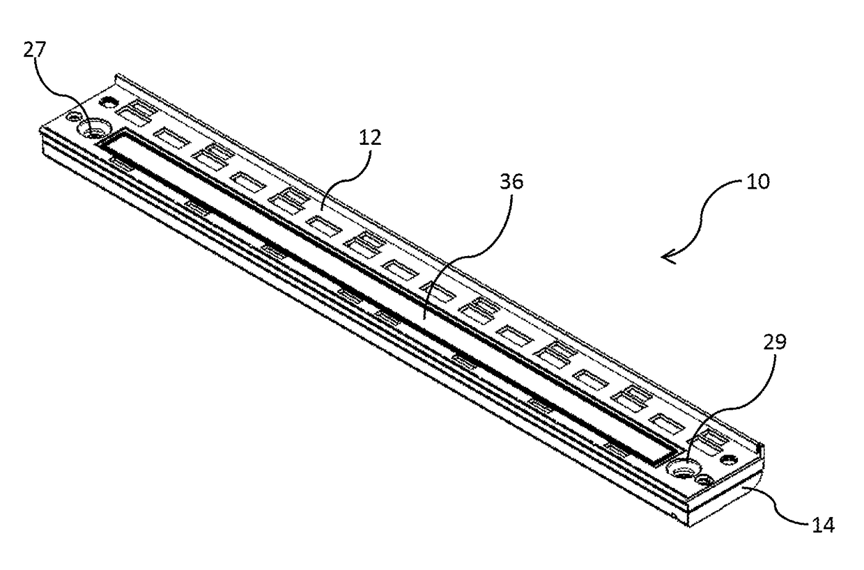
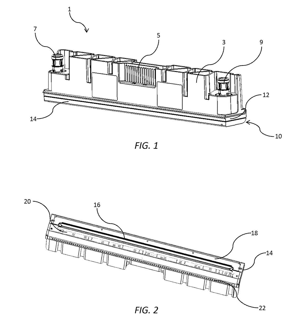
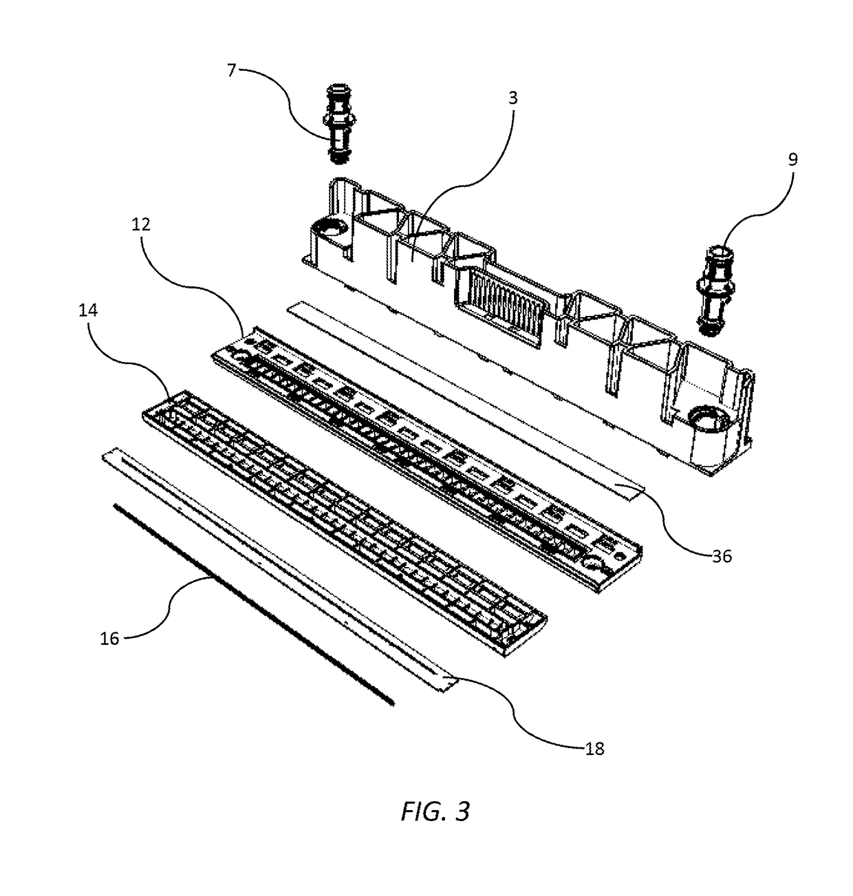
[0150]Referring now to FIGS. 10 to 16, in a first embodiment a base 41 of the lower ink manifold 14 comprises a floor 42 of the main ink channel 25, with the floor 42 defining a plurality of ink supply slots 44. The ink supply slots 44 receive ink from the main ink channel 25 and supply the ink into the backsides of the printhead chips 16 via the die-attach film 18. The ink supply slots 44 are longitudinally spaced apart along a length of the floor 42 and separated from each other by support webs, which take the form of diagonal joint webs 46 and transverse webs 48. The printhead chips 16 are attached to the base 41 of the lower ink manifold 14 via the adhesive die-attach film 18. The die-attach film 18 has a plurality of slot openings 50 mirroring the ink supply slots 44; and a plurality of film webs 52 mirroring the diagonal joint webs 46 and transverse webs 48 of the lower ink manifold 14.

[0151]The arrangement of the main ink channel 25 and ink supply slots 44 is designed to maxi...

second embodiment

[0154]Referring to FIGS. 17 to 22, in the lower ink manifold 14, the base 41 has a truss structure 60 supporting the printhead chips 16. The truss structure 60 has a first chord 62 and an opposite second chord 64, with a plurality of truss webs 66 extending between the two chords to define laterally flared ink outlets 61. The truss webs 66 are contiguously defined by a generally wavelike structure, which extends between the first and second chords 62 and 64 along the length of each printhead chip. Other truss configurations (e.g. regular diagonal webs) are, of course, within the ambit of the present invention.

[0155]The truss structure 60 provides excellent mechanical support for mounting the printhead chips 16. The truss webs 66 allow printhead chips 16 to be mounted to the base 41 of the lower ink manifold 14 with minimal chip cracking. Furthermore, the laterally flared ink outlets 61 are optimized for bubble venting as well as ink flow into the printhead chips.

[0156]As best shown ...


PUM


Abstract

An inkjet printhead including: an elongate fluid manifold having a base comprising a plurality of fluid delivery compartments, each compartment having a fluid outlet and a bubble-venting cavity; and one or more printhead chips attached to the base, each printhead chip receiving printing fluid from one or more fluid outlets. Each fluid outlet is aligned with a respective printhead chip and each bubble-venting cavity is offset from the respective printhead chip.

Description

CROSS-REFERENCE TO RELATED APPLICATIONS[0001]The present application claims the benefit of priority under 35 U.S.C. §119(e) of U.S. Provisional Application No. 62 / 330,776, entitled MONOCHROME INKJET PRINTHEAD CONFIGURED FOR HIGH-SPEED PRINTING, filed May 2, 2016 and of U.S. Provisional Application No. 62 / 377,467, entitled MONOCHROME INKJET PRINTHEAD CONFIGURED FOR HIGH-SPEED PRINTING, filed Aug. 19, 2016, the contents of each of which are hereby incorporated by reference in their entirety for all purposes.[0002]The present application is related to U.S. application Ser. No. ______ (Attorney Docket No. NXM010US), entitled PRINTER HAVING PRINTHEAD EXTENDING AND RETRACTING THROUGH MAINTENANCE MODULE, filed on even date herewith, to U.S. application Ser. No. ______ (Attorney Docket No. NXM001US), entitled INK DELIVERY SYSTEM FOR SUPPLYING INK TO MULTIPLE PRINTHEADS AT CONSTANT PRESSURE, filed on even date herewith, and to U.S. application Ser. No. ______ (Attorney Docket No. NXM002US), ...

Claims


Application Information

Patent Timeline
IPC IPC(8): B41J2/19B41J2/14
CPCB41J2/19B41J2002/14419B41J2/1433B41J2/515B41J2002/14362B41J2202/20B41J2/17546B41J2/155B41J2/17553B41J2/14B41J2/14145B41J2/14427B41J2202/21B41J2/045
Inventor JACKSON, GARRYBERRY, NORMANHUDSON, MICHAELBROWN, BRIANMALLINSON, SAMUELMCBAIN, GEORDIE
Owner MEMJET TECH LTD
Why Eureka
Try Eureka