Laser spot light with improved radiating structure

Inactive Publication Date: 2017-11-16
XI JUN
View PDF3 Cites 2 Cited by
  • Summary
  • Abstract
  • Description
  • Claims
  • Application Information

AI Technical Summary

Benefits of technology

The present invention relates to an improved laser spot light with a simplified radiating structure. The laser spot light includes a cylindrical shell, an inner radiator, laser heads, a light baffle, gratings, a gearbox, a mounting board, and a circuit board. The laser spot light also includes an outer radiator connected to the cylindrical shell and contacting with the inner radiator. The invention simplifies the radiating structure of the laser spot light to improve its performance and maintain normal operations of the laser heads.

Problems solved by technology

However, structures of these radiators are complicated and with large bulk.

Method used


Image

  • Laser spot light with improved radiating structure
  • Laser spot light with improved radiating structure
  • Laser spot light with improved radiating structure

Examples


Embodiment Construction

[0009]The invention will now be described in detail through several embodiments with reference to the accompanying drawings.

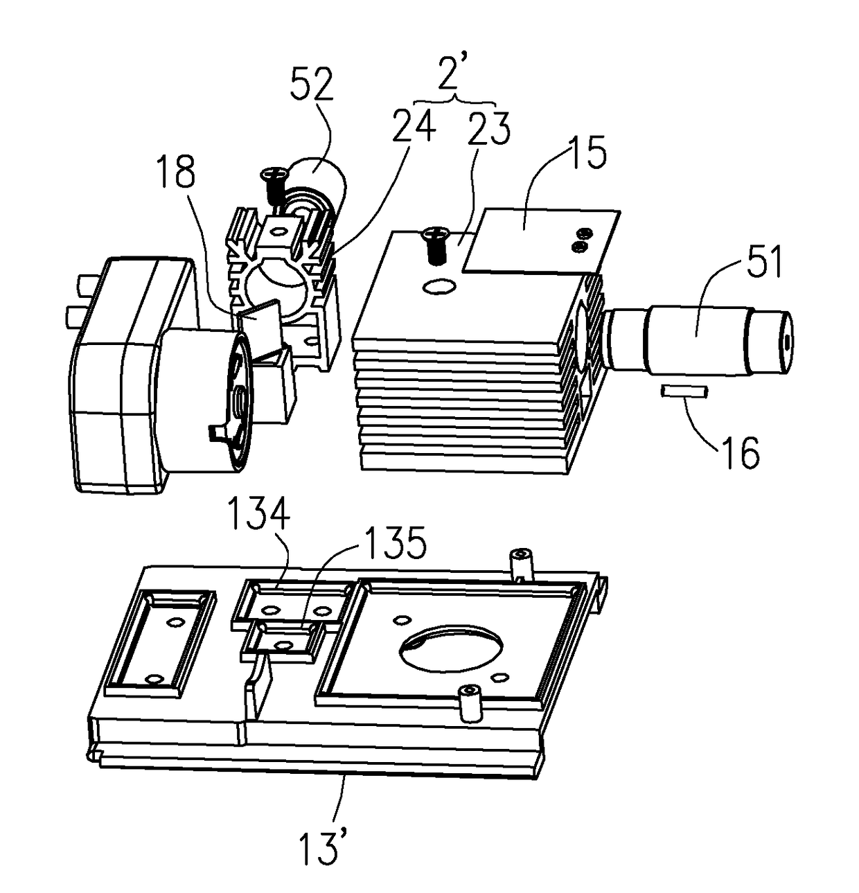
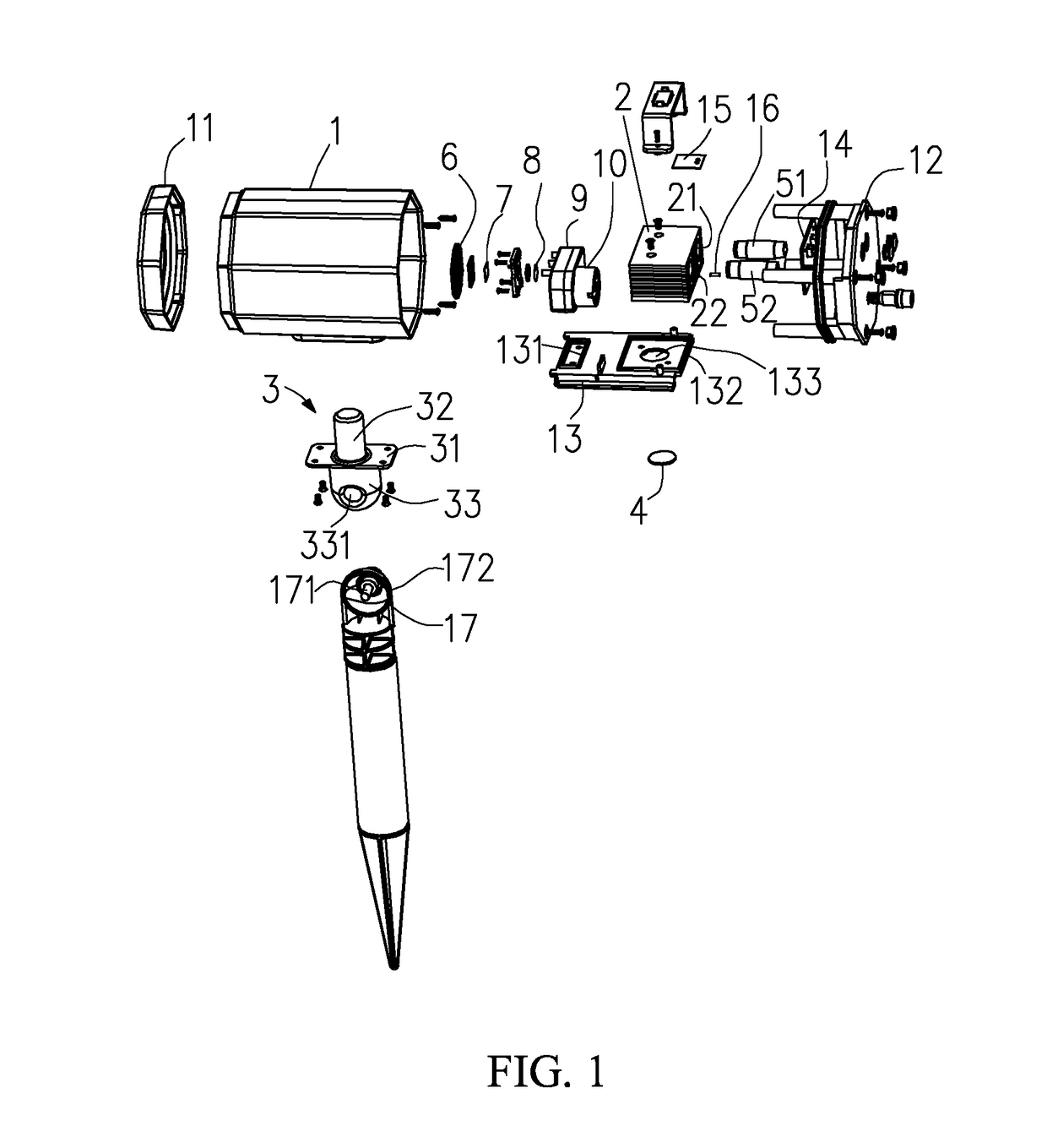
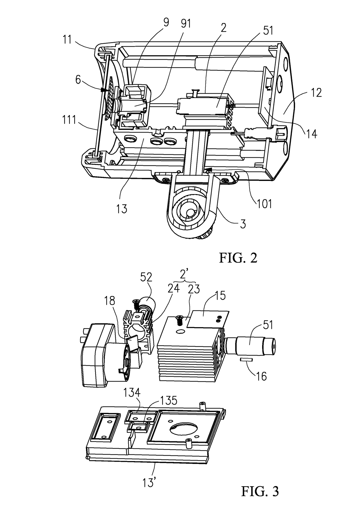
[0010]Please refer to FIG. 1 to FIG. 2, a laser spot light with improved radiating structure in accordance with an embodiment of the present invention includes a cylindrical shell 1 maily housing an inner radiator 2, two laser heads 51, 52, a light baffle 6, a first grating 7, a second grating 8, a gearbox 9, a motor 10, a mounting board 13 and a circuit board 14. The laser spot light further includes an outer radiator 3 connected to the cylindrical shell 1 and contacting with the inner radiator 2. In FIG. 2, a part of the cylindrical shell 1, the inner radiator 2, the outer radiator 3, the laser heads 51, 521, the light baffle 6, the first grating 7, the second grating 8, the gearbox 9, the mounting board 13 and the circuit board 14 is cut away, and the motor 10 is not shown.

[0011]The cylindrical shell 1 is substantially a hollow cylinder. An end surface of th...


PUM


Abstract

The present invention provides a laser spot light with improved radiating structure which includes a cylindrical shell, a mounting board fixed within the cylindrical shell, at least one laser head, an inner radiator made from heat-conductive metal and configured for supporting the at least one laser head and fixed on the mounting board, and an outer radiator made from heat-conductive metal and fixed to the side wall of the cylindrical shell with a part of the outer radiator passing across the cylindrical shell and touching with the inner radiator. Therefore an inner heat can be conducted to the outside of the cylindrical shell, and an operation temperature of the laser head can be maintained in a normal range.

Description

CROSS-REFERENCE TO RELATED APPLICATIONS[0001]The present application is a continuation-in-part of U.S. patent application Ser. No. 15 / 203,983, filed Jul. 7, 2016, which claims the benefit of CN Patent Application No. 201610207559.0, filed Apr. 1, 2016, and U.S. patent application Ser. No. 15 / 236,439, filed Aug. 14, 2016, which claims the benefit of CN Utility Patent Application No. 201620744193.6, filed Jul. 12, 2016, all of which are incorporated herein by reference in their entireties. The present application also claims the benefit of CN Patent Application No. 201620436630.8, filed May 12, 2016.BACKGROUND OF THE INVENTION1. Field of the Invention[0002]The present invention relates to outdoor illumination devices, and more particularly to a laser spot light with improved radiating structure.2. Description of Related Art[0003]Laser spot lights are commonly classified into laser spot lights with fixed / static raster images and cartoon laser spot lights utilizing motor dirving. Typica...

Claims


Application Information

Patent Timeline
IPC IPC(8): F21V29/70F21V14/08F21V11/08
CPCF21V29/70F21V14/08F21V11/08F21Y2115/30F21Y2113/10F21S8/003F21V21/0824F21V21/30F21W2131/105F21V29/74F21V29/89F21V29/90H01S5/06804H05B45/56
Inventor XI, JUN
Owner XI JUN
Why Eureka
Try Eureka